Asus DSEB-D16 SAS DSEB-D16 User's Manual for English Edition
Asus DSEB-D16 SAS Manual
 |
View all Asus DSEB-D16 SAS manuals
Add to My Manuals
Save this manual to your list of manuals |
Asus DSEB-D16 SAS manual content summary:
- Asus DSEB-D16 SAS | DSEB-D16 User's Manual for English Edition - Page 1
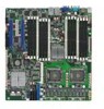
Motherboard DSEB-D16 Series DSEB-D16 DSEB-D16/SAS - Asus DSEB-D16 SAS | DSEB-D16 User's Manual for English Edition - Page 2
express written permission of ASUSTeK COMPUTER INC. ("ASUS"). Product warranty or service will not be extended if: (1) the ASUS HAS BEEN ADVISED OF THE POSSIBILITY OF SUCH DAMAGES ARISING FROM ANY DEFECT OR ERROR IN THIS MANUAL OR PRODUCT. SPECIFICATIONS AND INFORMATION CONTAINED IN THIS MANUAL - Asus DSEB-D16 SAS | DSEB-D16 User's Manual for English Edition - Page 3
viii About this guide ix Typography x DSEB-D16 Series specifications summary xi Chapter 1: Product introduction 1.1 Welcome 1-1 1.2 Package contents 1-1 1.3 Serial number label 1-2 1.4 Special features 1-2 1.4.1 Product highlights 1-2 1.4.2 Innovative ASUS features 1-4 Chapter 2: Hardware - Asus DSEB-D16 SAS | DSEB-D16 User's Manual for English Edition - Page 4
2-29 2.5.6 PCI-X slot (for ZCR slot; DSEB-D16/SAS only 2-30 2.5.7 SODIMM socket 2-31 2.6 Jumpers BIOS setup 4.1 Managing and updating your BIOS 4-1 4.1.1 Creating a bootable floppy disk 4-1 4.1.2 AFUDOS utility 4-2 4.1.3 ASUS CrashFree BIOS 3 utility 4-5 4.2 BIOS setup program 4-6 4.2.1 BIOS - Asus DSEB-D16 SAS | DSEB-D16 User's Manual for English Edition - Page 5
Chipset Configuration 4-16 4.4.3 PCI/PnP Configuration 4-20 4.4.4 USB Configuration 4-22 4.4.5 Peripheral Configuration 4-23 4.4.6 ACPI Configuration 4-24 4.4.7 Power On Configuration 4-25 4.4.8 Hardware Monitor 4-26 4.5 Server the RAID item in BIOS 5-2 5.1.4 RAID configuration utilities - Asus DSEB-D16 SAS | DSEB-D16 User's Manual for English Edition - Page 6
® 2000/Server 2003 6-22 6.5 Management applications and utilities installation 6-24 6.5.1 Running the support CD 6-24 6.5.2 Drivers menu 6-24 6.5.3 Management Software menu 6-25 6.5.4 Utilities menu 6-25 6.5.5 Contact information 6-25 Appendix: Reference information A.1 DSEB-D16/SAS model - Asus DSEB-D16 SAS | DSEB-D16 User's Manual for English Edition - Page 7
. This equipment generates, uses and can radiate radio frequency energy and, if not installed and used in accordance with manufacturer' s instructions, may cause harmful interference to radio communications. However, there is no guarantee that interference will not occur in a particular installation - Asus DSEB-D16 SAS | DSEB-D16 User's Manual for English Edition - Page 8
qualified service technician or your retailer. Operation safety • Before installing the motherboard and adding devices on it, carefully read all the manuals stable surface. • If you encounter technical problems with the product, contact a qualified service technician or your retailer. This symbol of - Asus DSEB-D16 SAS | DSEB-D16 User's Manual for English Edition - Page 9
that you may refer to when configuring the motherboard. Where to find more information Refer to the following sources for additional information and for product and software updates. 1. ASUS websites The ASUS website provides updated information on ASUS hardware and software products. Refer to the - Asus DSEB-D16 SAS | DSEB-D16 User's Manual for English Edition - Page 10
the following symbols used throughout this manual. DANGER/WARNING: Information to prevent injury to yourself when trying to complete a task. CAUTION: Information to prevent damage to the components when trying to complete a task. IMPORTANT: Instructions that you MUST follow to complete - Asus DSEB-D16 SAS | DSEB-D16 User's Manual for English Edition - Page 11
specifications summary Model Name DSEB-D16/SAS DSEB-D16 Processor / System Bus 2 * Socket LGA771 Dual-Core Intel® Xeon® Processor 5000/5100/5200 Quad-Core Intel® Xeon® Processor 5300/5400 Sequence FSB 1066/1333/1600MHz EM64T Core Logic 2x2M, 4M, 6M, 8M & 12M L2 cache Intel® 5400 Memory - Asus DSEB-D16 SAS | DSEB-D16 User's Manual for English Edition - Page 12
DSEB-D16 Series specifications summary Storage Networking Graphic Onboard I/O Connectors Rear I/O Connectors Management Solution Monitoring Environment SAS SAS controller: LSI® Integrated RAID 0, 1, 1E support Optional LSI® ZCR (Zero-Channel-RAID) -- PCI-X card: (For upgrade to support - Asus DSEB-D16 SAS | DSEB-D16 User's Manual for English Edition - Page 13
This chapter describes the motherboard introPdruoc1dtuiocnt features and the new technologies it supports. - Asus DSEB-D16 SAS | DSEB-D16 User's Manual for English Edition - Page 14
Chapter summary 1 1.1 Welcome 1-1 1.2 Package contents 1-1 1.3 Serial number label 1-2 1.4 Special features 1-2 ASUS DSEB-D16 Series - Asus DSEB-D16 SAS | DSEB-D16 User's Manual for English Edition - Page 15
Retail Pack Bulk Pack DSEB-D16/ SAS DSEB-D16 DSEB-D16/ SAS DSEB-D16 6 6 -- -- 3 3 -- -- 2 -- -- -- 1 1 -- -- 1 1 1 1 2 2 2 2 1 -- 1 -- 1 -- 1 -- 1 -- 1 -- 1 -- 1 -- Application CD Support CD 1 1 1 1 Documentation User Guide Packing Qty. 1 3pcs per - Asus DSEB-D16 SAS | DSEB-D16 User's Manual for English Edition - Page 16
serial number of the product, ASUS Technical Support team members can then offer a quicker and satisfying solution to your problems. DSEB-D16 xxM0Axxxxxxx Made in China 合格 1.4 Special features 1.4.1 Product highlights Latest processor technology The motherboard comes with two LGA-771 sockets - Asus DSEB-D16 SAS | DSEB-D16 User's Manual for English Edition - Page 17
. PCIe 2.0 This motherboard supports the latest PCIe 2.0 device for twice the current speed and bandwidth. This enhances system performance while still providing backward compatibility to PCIe 1.0 devices. Serial Attached SCSI (SAS) technology support (DSEB-D16/SAS model only) SAS is the latest - Asus DSEB-D16 SAS | DSEB-D16 User's Manual for English Edition - Page 18
than current server platforms. All High-quality Conductive Polymer Capacitors This motherboard uses all high-quality conductive polymer capacitors onboard for durability, improved lifespan, and enhanced thermal capacity. 90% + Power Efficiency Compared with the non-green design platform, ASUS's new - Asus DSEB-D16 SAS | DSEB-D16 User's Manual for English Edition - Page 19
This chapter lists the hardware setup procedures that you have to perform when installing system components. It includes description of the jumpers and connectors on the motherboard. 2 Hardware information - Asus DSEB-D16 SAS | DSEB-D16 User's Manual for English Edition - Page 20
Chapter summary 2 2.1 Before you proceed 2-1 2.2 Motherboard overview 2-3 2.3 Central Processing Unit (CPU 2-11 2.4 System memory 2-16 2.5 Expansion slots 2-28 2.6 Jumpers 2-32 2.7 Connectors 2-37 ASUS DSEB-D16 Series - Asus DSEB-D16 SAS | DSEB-D16 User's Manual for English Edition - Page 21
that you should shut down the system and unplug the power cable before removing or plugging in any motherboard component. The illustration below shows the location of the onboard LED ® SB_PWR1 DSEB-D16 Series Onboard LED ON Standby Power (green) OFF Powered Off ASUS DSEB-D16 Series 2-1 - Asus DSEB-D16 SAS | DSEB-D16 User's Manual for English Edition - Page 22
CPU warning LED lights up, the motherboard will not boot. 3. Hearbeat LED (for DSEB-D16/SAS only) The green heartbeat LED blinks per second to indicate that the LSI 1068 chipset is working normally. ® LED1 DSEB-D16 Series Heart Beat LED ON LSI SAS 1068 starts working 2-2 Chapter 2: Hardware - Asus DSEB-D16 SAS | DSEB-D16 User's Manual for English Edition - Page 23
in the image below. 2.2.2 Screw holes Place nine (9) screws into the holes indicated by circles to secure the motherboard to the chassis. DO NOT overtighten the screws! Doing so can damage the motherboard. Place this side towards the rear of the chassis ® DSEB-D16 ASUS DSEB-D16 Series 2-3 - Asus DSEB-D16 SAS | DSEB-D16 User's Manual for English Edition - Page 24
breakage due to the weight of the CPU heatsinks, your motherboard package comes with CEK springs that you can use as weight support. Install the CEK springs before installing the motherboard. We strongly recommend you use SSI CEB 1.1 compliant chassis. Otherwise, the CPU cooler cannot be mounted - Asus DSEB-D16 SAS | DSEB-D16 User's Manual for English Edition - Page 25
, repeat steps 2 to 4 to install the CEK spring to the CPU2 heatsink holes. The CEK springs appear as shown when installed. CEK spring screw hole ASUS DSEB-D16 Series 2-5 - Asus DSEB-D16 SAS | DSEB-D16 User's Manual for English Edition - Page 26
into the chassis, locate the standoffs that should match the eight (8) CEK spring screw holes. 7. Install the motherboard with the external I/O ports toward the chassis rear panel. The CPU sockets should be right on top of their respective standoffs. Standoffs for CPU1 Standoffs - Asus DSEB-D16 SAS | DSEB-D16 User's Manual for English Edition - Page 27
2.2.4 Motherboard layouts DSEB-D16/SAS model COM1 PS/2 T: Mouse B: Keyboard USB1 USB2 FBD_FAN1 REAR_FAN1 REAR_FAN2 33cm (13in) PSUSMB1 ATXPWR1 ATX12V2 DDR Intel® SAS2 6321ESB SAS1 SB_PWR1 CPU_WARN1 CPU_FAN2 FRNT_FAN1 FRNT_FAN2 FRNT_FAN4 30.5cm (12in) FRNT_FAN3 ASUS DSEB-D16 Series 2-7 - Asus DSEB-D16 SAS | DSEB-D16 User's Manual for English Edition - Page 28
pin module) DDR FB-DIMM_01 (64/72 bit, 240-pin module) DDR FB-DIMM_00 (64/72 bit, 240-pin module) CPU_FAN1 CPU1 ATX12V1 VGA1 ® DSEB-D16 RJ-45 (LAN12) RJ-45 (LAN34) LAN_EN1 Intel LAN_EN3 82563EB LAN_EN4 Intel 82573L Intel 82573L P1V8_SEL1 P1V5_SEL1 Intel® 5400MCH FBD_FAN2 DDR FB-DIMM_20 (64 - Asus DSEB-D16 SAS | DSEB-D16 User's Manual for English Edition - Page 29
S/W RAID setting (3-pin RAID_SEL1) (DSEB-D16 model only) 6. Onboard storage setting (3-pin SAS_EN1) (DSEB-D16/SAS model only) 7. Force BIOS recovery setting (3-pin RECOVERY1) 8. P1V5 ) ports 8. LAN 3/4 (RJ-45) ports Page 2-37 2-37 2-37 2-37 2-37 2-37 2-37 2-37 ASUS DSEB-D16 Series 2-9 - Asus DSEB-D16 SAS | DSEB-D16 User's Manual for English Edition - Page 30
SATA1, SATA2, SATA3, SATA4, SATA5, SATA6 ) 4. SAS LSI1068 ports LED connector (18-1 pin SASLED1) (DSEB-D16/SAS model only) 5. SAS connectors (DSEB-D16/SAS model only) 6. Serial General Purpose Input/Output connector (6-1 pin SGPIO1) (DSEB-D16 model only) 7. Hard disk activity LED connector - Asus DSEB-D16 SAS | DSEB-D16 User's Manual for English Edition - Page 31
the cap after installing the motherboard. ASUS will process Return Merchandise Authorization (RMA) requests only if the motherboard comes with the cap To install a CPU: 1. Locate the CPU socket on the motherboard. CPU1 CPU2 ® DSEB-D16 Series CPU LGA771 • Before installing the CPU, make sure that - Asus DSEB-D16 SAS | DSEB-D16 User's Manual for English Edition - Page 32
2. Press the load lever with your thumb (A), then move it to the left (B) until it is released from the retention tab. Retention tab A Load lever PnP cap B This side of the socket box should face you. To prevent damage to the socket pins, do not remove the PnP cap unless you are installing a - Asus DSEB-D16 SAS | DSEB-D16 User's Manual for English Edition - Page 33
the system and enter the BIOS Setup (see Chapter 4: BIOS setup). Under the Advanced Menu, make sure that the item Hyper‑Threading Technology is set to Enabled. The item appears only if you installed a CPU that supports Hyper-Threading Technology. 3. Reboot the computer. ASUS DSEB-D16 Series 2-13 - Asus DSEB-D16 SAS | DSEB-D16 User's Manual for English Edition - Page 34
the top of the CPU before installing the heatsink and fan. • Refer to the installation manual that came with the CPU package for details on heatsink/fan assembly and installation. CPU heatsink heatsink align with the nuts on the support plate. Heatsink screw 2-14 Chapter 2: Hardware information - Asus DSEB-D16 SAS | DSEB-D16 User's Manual for English Edition - Page 35
4. Repeat steps 1 to 3 to install the other heatsink if you have installed a second CPU, then connect the fan cable to the 4‑pin connector labeled CPU_FAN1. ASUS DSEB-D16 Series 2-15 - Asus DSEB-D16 SAS | DSEB-D16 User's Manual for English Edition - Page 36
on an FB-DIMM socket. Note that an FB-DIMM socket has an Advanced Memory Buffer (AMB) chip that allows memory-to-CPU connection at gigabit speed. The figure illustrates the location of the FB-DIMM sockets: ® DSEB-D16 Series 240-pin FB-DIMM sockets 128 Pins 112 Pins FB-DIMM_13 FB-DIMM_12 FB - Asus DSEB-D16 SAS | DSEB-D16 User's Manual for English Edition - Page 37
should be installed on the same slot number for each channel. For example, you may install the same type of DIMMs in DIMM_00, and DIMM_10. ASUS DSEB-D16 Series 2-17 - Asus DSEB-D16 SAS | DSEB-D16 User's Manual for English Edition - Page 38
technology The Intel® 5400 chipset supports the memory mirroring and sparing technology. Refer to the below sections: Memory Mirroring When enabling memory mirroring function in the BIOS setting (refer to section 4.4.2 Chipset Configuration and configure the option Memory Branch Mode as Mirror - Asus DSEB-D16 SAS | DSEB-D16 User's Manual for English Edition - Page 39
1 Slot 2 Slot 3 Ch:3 Ch:2 Ch:0 Ch:1 Configuration 3 (Mirroring) : Twelve memories population DIMMs are installed in the following slots: DIMM_00, DIMM_01, DIMM_02, DIMM_10, DIMM_11, DIMM_12, 0 Slot 1 Slot 2 Slot 3 Slot 0 Slot 1 Slot 2 Slot 3 Ch:3 Ch:2 ASUS DSEB-D16 Series Ch:0 Ch:1 2-19 - Asus DSEB-D16 SAS | DSEB-D16 User's Manual for English Edition - Page 40
-12 DIMM_11 DIMM_10 DIMM_03 DIMM_02 DIMM_01 DIMM_00 DIMM_20 DIMM_21 DIMM_22 DIMM_23 DIMM_30 DIMM_31 DIMM_32 DIMM_33 Configuration 4 (Mirroring) : Sixteen memories population DIMMs are installed in the following slots: DIMM_00, DIMM_01, DIMM_02, DIMM_03, DIMM_10, DIMM_11, DIMM_12, DIMM_13, DIMM_20 - Asus DSEB-D16 SAS | DSEB-D16 User's Manual for English Edition - Page 41
Chipset Configuration and configure the options of Branch 0 Rank Sparing or Branch 1 Rank Sparing to enable the memory sparing functions. The default BIOS setting is disabled. • Each branch contains its own sparing engine and can be enabled or disabled separately. • This motherboard does not support - Asus DSEB-D16 SAS | DSEB-D16 User's Manual for English Edition - Page 42
) Rank 0 Rank 1 (1024 MB) (1024 MB) 1024 MB 4096 MB 1024 MB Three DIMMs per channel Sparing Memory space Branch0 Sparing Memory space Sparing Memory space Total Memory Channel 0 DIMM_00 (512MB*2 Ranks) Rank 0 Rank 1 (512 MB) (512 MB) Channel 1 DIMM_10 (512MB*2 Ranks) Rank 0 Rank - Asus DSEB-D16 SAS | DSEB-D16 User's Manual for English Edition - Page 43
Four DIMMs per channel (Dual ranks) Sparing Memory space Branch0 Sparing Memory space Sparing Memory space Sparing Memory space Total Memory Channel 0 DIMM_00 (512MB*2 Ranks) Rank 0 Rank 1 (512 MB) (512 ) Rank 0 Rank 1 (4096 MB) (4096 MB) 4096 MB 22528 4096 MB ASUS DSEB-D16 Series 2-23 - Asus DSEB-D16 SAS | DSEB-D16 User's Manual for English Edition - Page 44
components. Failure to do so may cause severe damage to both the motherboard and the components. To install a DIMM: 1. Unlock a DIMM socket into a socket to avoid damaging the DIMM. • The FB-DIMM sockets do not support DDR2 DIMMs. DO NOT install DDR2 DIMMs to the FB-DIMM sockets. 2.4.5 Removing a - Asus DSEB-D16 SAS | DSEB-D16 User's Manual for English Edition - Page 45
-DIMM fan. To install the optional FB-DIMM fan: 1. Locate the three FB-DIMM fan holes on the motherboard. 2. Disengage the fan top cover from the fan base. You can do this by firmly gripping the top cover legs into the FB-DIMM holes until the legs are securely in place. ASUS DSEB-D16 Series 2-25 - Asus DSEB-D16 SAS | DSEB-D16 User's Manual for English Edition - Page 46
the cables pass through the notch on the fan base as shown. 5. Connect the fan cable to the 4-pin connector labeled FBD_FAN1. 6. Repeat the previous instructions to install the other FB-DIMM fan if needed. 2-26 Chapter 2: Hardware information - Asus DSEB-D16 SAS | DSEB-D16 User's Manual for English Edition - Page 47
-DIMM fan 1. Unplug the fan cable. 2. Grip the top cover clamps until the top cover hooks are released, then carefully lift the top cover while supporting the fan base with your free hand. 3. Carefully lift the fan base. Top cover clamp ASUS DSEB-D16 Series 2-27 - Asus DSEB-D16 SAS | DSEB-D16 User's Manual for English Edition - Page 48
Remove the system unit cover (if your motherboard is already installed in a chassis). 3. BIOS setup. 2. Assign an IRQ to the card. Refer to the tables on the next page. 3. Install the software drivers for the expansion card. When using PCI cards on shared slots, ensure that the drivers support - Asus DSEB-D16 SAS | DSEB-D16 User's Manual for English Edition - Page 49
slots, which support the latest PCIe 2.0 device for twice the current speed and bandwidth, are designed for various server class high performance add-on server class high performance add-on cards like SCSI RAID card, fiber-channel card, etc. PCIEx16 slot PCI slot PCIEx16 slot ASUS DSEB-D16 Series 2- - Asus DSEB-D16 SAS | DSEB-D16 User's Manual for English Edition - Page 50
ZCR slot; DSEB-D16/SAS only) The 64bit PCI-X slot on the motherboard supports a Zero-Channel RAID card that allows RAID0, RAID1, RAID10 and RAID 5 configurations. PCIX4 Slot ZCR bracket holder (1U) ZCR bracket holder (2U and above) If you want to install the motherboard to a 1U server system, you - Asus DSEB-D16 SAS | DSEB-D16 User's Manual for English Edition - Page 51
for DSEB-D16/SAS onboard LSI 1068 SAS controller is LSI MegaRAID SAS 8300XLP card. Visit the LSI LOGIC website (www.lsilogic. com) for more information. 2.5.7 SODIMM socket The SODIMM socket on the motherboard supports an ASUS® Server Management Board 3 Series (ASMB3). SODIMM socket ASUS DSEB-D16 - Asus DSEB-D16 SAS | DSEB-D16 User's Manual for English Edition - Page 52
Clock (RTC) RAM in CMOS. You can clear the CMOS memory of date, time, and system setup parameters by erasing the Hold down the key during the boot process and enter BIOS setup to re-enter data. Except when clearing the RTC RAM DSEB-D16 Series Clear RTC RAM 2-32 Chapter 2: Hardware information - Asus DSEB-D16 SAS | DSEB-D16 User's Manual for English Edition - Page 53
VGA controller. Set to pins 1-2 to activate the VGA feature. ® DSEB-D16 Series VGA setting VGA_EN1 12 23 Enable (Default) Disable 3. LAN . LAN_EN1 12 23 Enable (Default) Disable ® LAN_EN3 12 23 DSEB-D16 Series LAN setting Enable (Default) Disable LAN_EN4 12 23 Enable ( - Asus DSEB-D16 SAS | DSEB-D16 User's Manual for English Edition - Page 54
at full speed. 5. Intel® 6321ESB SATA port S/W RAID setting (3-pin RAID_SEL1) (DSEB-D16 model only) This jumper allows you to select the Serial ATA RAID configuration utility to use when you create disk arrays. Both utilities are supported by the Intel® 6321ESB. Place the jumper caps on pins 1-2 if - Asus DSEB-D16 SAS | DSEB-D16 User's Manual for English Edition - Page 55
the motherboard (XXXXXX.ROM) and the AFUDOS.EXE utility. 2. Set the jumper to pins 2-3. 3. Insert the floppy disk then turn on the system to update the BIOS. 4. Shut down the system. 5. Set the jumper back to pins 1-2. 6. Turn on the system. RECOVERY1 12 23 Normal (Default) DSEB-D16 Series BIOS - Asus DSEB-D16 SAS | DSEB-D16 User's Manual for English Edition - Page 56
adjust the voltage supply for the FB-DIMM. If you are installing the low-voltage FB-DIMMs, move the jumper cap to corresponding pins. ® ® DSEB-D16 Series P1V5 setting P1V5_SEL1 12 23 1.5V (Default) 1.1V 9. P1V8 setting (3-pin P1V8_SEL1) This jumper allows you to adjust the voltage supply for - Asus DSEB-D16 SAS | DSEB-D16 User's Manual for English Edition - Page 57
BLINKING Data activity Speed LED Status Description OFF 10 Mbps connection ORANGE 100 Mbps connection GREEN 1 Gbps connection ACT/LINK SPEED LED LED LAN port ASUS DSEB-D16 Series 2-37 - Asus DSEB-D16 SAS | DSEB-D16 User's Manual for English Edition - Page 58
cable to PIN 1. DSEB-D16 Series Floppy disk drive connector 2. IDE connector (40-1 pin PRI_IDE1) This connector is for an Ultra DMA 100/66 signal cable. The Ultra DMA 100/66 signal cable has three connectors: a blue connector for the primary IDE connector on the motherboard, a black connector for - Asus DSEB-D16 SAS | DSEB-D16 User's Manual for English Edition - Page 59
39 ASUS DSEB-D16 Series SASLED1 PIN1 DSEB-D16 Series SASLED connector ® FLT_LED0 FLT_LED1 FLT_LED2 FLT_LED3 GND FLT_LED4 FLT_LED5 FLT_LED6 FLT_LED7 ACT_LED0 ACT_LED1 ACT_LED2 ACT_LED3 ACT_LED4 ACT_LED5 ACT_LED6 ACT_LED7 4. SAS LSI1068 ports LED connector (18-1 pin SASLED1) (DSEB-D16/SAS model - Asus DSEB-D16 SAS | DSEB-D16 User's Manual for English Edition - Page 60
5. SAS connectors (DSEB-D16/SAS model only) This motherboard comes with two Serial Attached SCSI (SAS) connectors, the next-generation storage technology that supports both Series SCSI and Serial ATA (SATA). Each connector supports one device. ® DSEB-D16 Series SAS connectors To connect the SAS - Asus DSEB-D16 SAS | DSEB-D16 User's Manual for English Edition - Page 61
-D16 Series SGPIO connector 7. Hard disk activity LED connector (4-pin HDLED1) This connector is used to connect to a hard disk drive active LED connector on the SCSI or RAID card. PIN1 HDLED1 DSEB-D16 Series storage card activity LED connector ® NC ADD_IN_CARDADD_IN_CARDNC ASUS DSEB-D16 Series - Asus DSEB-D16 SAS | DSEB-D16 User's Manual for English Edition - Page 62
of the system chassis. This USB connector complies with USB 2.0 specification that supports up to 480 Mbps connection speed. Power USB PortB(-) USB PortB(+) GND NC ® Power USB PortA(-) USB PortA(+) GND USB34 PIN1 DSEB-D16 Series USB connector The USB port module is purchased separately. 9. CPU - Asus DSEB-D16 SAS | DSEB-D16 User's Manual for English Edition - Page 63
module to a slot opening at the back of the system chassis. ® ® COM2 PIN1 DSEB-D16 Series Serial port connector The serial port module is purchased separately. 11. LPC debug card connector 3V GND LPC_LAD3 LPC_LAD1 LFRAME_N GND DSEB-D16 Series LPC debug card connector ASUS DSEB-D16 Series 2-43 - Asus DSEB-D16 SAS | DSEB-D16 User's Manual for English Edition - Page 64
SMBus connector (5-pin PSUSMB1) This connector is for the power supply SMB cable, if your power supply supports the SMBus function. PSUSMB1 ® I2C_7_CLK# I2C_7_DATA# NC GND +3.3V Remote Sense DSEB-D16 Series Power supply SMBus connector 13. SSI power connectors (24-pin ATXPWR1, 8-pin ATX12V1, 4-pin - Asus DSEB-D16 SAS | DSEB-D16 User's Manual for English Edition - Page 65
on the BIOS settings. Pressing the power switch for more than four seconds while the system is ON turns the system OFF. 6. Reset button (Blue 2-pin RESET) This 2-pin connector is for the chassis-mounted reset button for system reboot without turning off the system power. ASUS DSEB-D16 Series 2-45 - Asus DSEB-D16 SAS | DSEB-D16 User's Manual for English Edition - Page 66
CASEOPEN GND LOCATORLED1+ LOCATORLED1- LOCATORBTN# GND LOCATORLED2LOCATORLED2+ DSEB-D16 Series Auxiliary panel connector 3 454 1. Front panel When you remove any chassis component, the sensor triggers and sends a high-level signal to these leads to record a chassis intrusion event. The default - Asus DSEB-D16 SAS | DSEB-D16 User's Manual for English Edition - Page 67
This chapter describes the power up Powerin3g up sequence, and ways of shutting down the system. - Asus DSEB-D16 SAS | DSEB-D16 User's Manual for English Edition - Page 68
Chapter summary 3 3.1 Starting up for the first time 3-1 3.2 Turning off the computer 3-2 ASUS DSEB-D16 Series - Asus DSEB-D16 SAS | DSEB-D16 User's Manual for English Edition - Page 69
followed by four short beeps Description VGA detected Quick boot set to disabled No keyboard detected No memory detected No VGA detected Hardware component failure 7. At power on, hold down the key to enter the BIOS Setup. Follow the instructions in Chapter 4. ASUS DSEB-D16 Series 3-1 - Asus DSEB-D16 SAS | DSEB-D16 User's Manual for English Edition - Page 70
is ON, pressing the power switch for less than four seconds puts the system to sleep mode or to soft-off mode, depending on the BIOS setting. Pressing the power switch for more than four seconds lets the system enter the soft-off mode regardless of the - Asus DSEB-D16 SAS | DSEB-D16 User's Manual for English Edition - Page 71
This chapter tells how to change the system settings through the BIOS Setup BIOS se4tup menus. Detailed descriptions of the BIOS parameters are also provided. - Asus DSEB-D16 SAS | DSEB-D16 User's Manual for English Edition - Page 72
Chapter summary 4 4.1 Managing and updating your BIOS 4-1 4.2 BIOS setup program 4-6 4.3 Main menu 4-9 4.4 Advanced menu 4-14 4.5 Server menu 4-28 4.6 Security menu 4-30 4.7 Boot menu 4-32 4.8 Exit menu 4-34 ASUS DSEB-D16 Series - Asus DSEB-D16 SAS | DSEB-D16 User's Manual for English Edition - Page 73
update the motherboard Basic Input/Output System (BIOS) setup: 1. ASUS AFUDOS (Updates the BIOS in DOS mode using a bootable floppy disk.) 2. ASUS CrashFree BIOS 3 (To recover the BIOS using a bootable floppy disk when the BIOS the format options field, then click Start. ASUS DSEB-D16 Series 4-1 - Asus DSEB-D16 SAS | DSEB-D16 User's Manual for English Edition - Page 74
BIOS screens are for reference only. The actual BIOS screen displays may not be the same as shown. 1. Copy the AFUDOS utility (afudos.exe) from the motherboard support copies the current BIOS file to the floppy disk. A:\>afudos /oOLDBIOS1.rom AMI Firmware Update Utility - Version 1.19(ASUS V2.07(03 - Asus DSEB-D16 SAS | DSEB-D16 User's Manual for English Edition - Page 75
!! Do not turn off power during flash BIOS Reading file ....... done Reading flash ...... done Advance Check ...... Erasing flash ...... done Writing flash ...... 0x0008CC00 (9%) DO NOT shut down or reset the system while updating the BIOS to prevent system boot failure! ASUS DSEB-D16 Series 4-3 - Asus DSEB-D16 SAS | DSEB-D16 User's Manual for English Edition - Page 76
the motherboard support CD to the optical drive. 3. Boot the system from the support CD, then select the FreeDOS command prompt. 4. At the DOS prompt, replace the prompt with the USB flash disk drive letter, then type: afudos /i[filename]. 3. Follow the instructions in the previous section to update - Asus DSEB-D16 SAS | DSEB-D16 User's Manual for English Edition - Page 77
the BIOS recovery finished. DO NOT shut down or reset the system while recovering the BIOS! Doing so would cause system boot failure! The recovered BIOS may not be the latest BIOS version for this motherboard. Visit the ASUS website (www.asus.com) to download the latest BIOS file. ASUS DSEB-D16 - Asus DSEB-D16 SAS | DSEB-D16 User's Manual for English Edition - Page 78
setup program This motherboard supports a programmable Low-Pin Count (LPC) chip that you can update using the provided utility described in section 4.1 Managing and updating your BIOS. Use the BIOS Setup program when you are installing a motherboard, reconfiguring your system, or prompted to "Run - Asus DSEB-D16 SAS | DSEB-D16 User's Manual for English Edition - Page 79
menu screen Menu items Menu bar Configuration fields General help Main Advanced BIOS SETUP UTILITY Server Security Boot Exit System Date [Thu, 10/11/2007] System Time [11:07:30] the settings. Some of the navigation keys differ from one screen to another. ASUS DSEB-D16 Series 4-7 - Asus DSEB-D16 SAS | DSEB-D16 User's Manual for English Edition - Page 80
4.2.4 Menu items The highlighted item on the menu bar displays the specific items for that menu. For example, selecting Main shows the Main menu items. The other items (Advanced, At the top right corner of the menu screen is a brief description of the selected item. 4-8 Chapter 4: BIOS setup - Asus DSEB-D16 SAS | DSEB-D16 User's Manual for English Edition - Page 81
information on the menu screen items and how to navigate through them. Main Advanced BIOS SETUP UTILITY Server Security Boot Exit System Date [Mon, 11/12/2007] System Time [11:07 options: [Disabled] [360 KB 5¼"] [1.2 MB 5.¼"] [720 KB 3½"] [1.44 MB 3½"] [2.88 MB 3½"] ASUS DSEB-D16 Series 4-9 - Asus DSEB-D16 SAS | DSEB-D16 User's Manual for English Edition - Page 82
you wish to configure the item. Main BIOS SETUP UTILITY IDE Configuration ATA/IDE Configuration Sets the configuration for the Serial ATA connectors supported by the Southbridge chip. Configuration options: [ AHCI] option allows the onboard storage driver to enable advanced Serial ATA features - Asus DSEB-D16 SAS | DSEB-D16 User's Manual for English Edition - Page 83
American Megatrends, Inc. The BIOS automatically detects the values opposite the Select [CDROM] if you are specifically configuring a CD-ROM drive. supports this mode, and if the device was not previously formatted with LBA mode disabled. Configuration options: [Disabled] [Auto] ASUS DSEB-D16 - Asus DSEB-D16 SAS | DSEB-D16 User's Manual for English Edition - Page 84
if the device supports multi-sector transfer feature specifications. The BIOS automatically detects the items in this menu. Main System Information BIOS SETUP UTILITY Model Name ASUS DSEB-D16/SAS Model ID 8064A0 ASUS-BIOS Version Date 1000.006 11/06/2007 Processor Information System Memory - Asus DSEB-D16 SAS | DSEB-D16 User's Manual for English Edition - Page 85
, Inc. System Memory Displays the installed system memory information. Main System Memory Information BIOS SETUP UTILITY Type : DDR2 533 Total Memory: 1024MB DIMM_00 - General Help F10 Save and Exit ESC Exit v02.61 (C)Copyright 1985-2006, American Megatrends, Inc. ASUS DSEB-D16 Series 4-13 - Asus DSEB-D16 SAS | DSEB-D16 User's Manual for English Edition - Page 86
BIOS SETUP UTILITY Server Security Boot WARNING: Setting wrong values in the below sections may cause system to malfunction. CPU Configuration Chipset not support the related functions. Advanced BIOS SETUP UTILITY Configure advanced CPU settings Ratio CMOS Setting C1E Support Hardware - Asus DSEB-D16 SAS | DSEB-D16 User's Manual for English Edition - Page 87
Setting this item to [Enabled] allows legacy operating systems to boot even without support for CPUs with extended CPUID functions. Configuration options: [Disabled] [Enabled] Virtualization ] [Enabled] Items above with * mark are for technical personnel to debug only. ASUS DSEB-D16 Series 4-15 - Asus DSEB-D16 SAS | DSEB-D16 User's Manual for English Edition - Page 88
the Northbridge settings. Advanced BIOS SETUP UTILITY NorthBridge Chipset Configuration MCH Branch Mode Patrol Scrubbing Demand Scrubbing Branch Dependent Sparing Branch 0 Branch Specific Sparing Rank Interleaving Branch 1 Branch Specific Sparing Rank Interleaving MemCool - Asus DSEB-D16 SAS | DSEB-D16 User's Manual for English Edition - Page 89
three items will be grayed out. Configuration options: [Disabled] [Enabled] Branch Specific Sparing [Disabled] Allows you to enable or disable the DIMM sparing feature. Configuration or disable Intel QuickData Tech. function. Configuration options: [Enabled] [Disabled] ASUS DSEB-D16 Series 4-17 - Asus DSEB-D16 SAS | DSEB-D16 User's Manual for English Edition - Page 90
], the target link speed will be forced to meet the PCIe Gen1 specification. Configuration options: [Auto] [PCIe Gen1] PCIE1 Slot Payload Size [Auto] options: [Auto] [128B] [256B] Inel VT-d Configuration Advanced BIOS SETUP UTILITY Intel VT-d [Disabled] Intel VT-d function en ←→ Select - Asus DSEB-D16 SAS | DSEB-D16 User's Manual for English Edition - Page 91
Advanced BIOS SETUP UTILITY South Bridge Chipset Configuration ESB2 PCI-X Hub Configuration ESB2 Bus-M PCI-X Hub configuration options. ESB2 PCI-X Hub Configuration Advanced BIOS SETUP of VGA for the devices behind PXH. Configuration options: [Disabled] [Enabled] ASUS DSEB-D16 Series 4-19 - Asus DSEB-D16 SAS | DSEB-D16 User's Manual for English Edition - Page 92
resources for either PCI/PnP or legacy ISA devices, and setting the memory size block for legacy ISA devices. Take caution when changing the settings options: [No] [Yes] Plug And Play O/S [No] When set to [No], BIOS configures all the devices in the system. When set to [Yes] and if you install - Asus DSEB-D16 SAS | DSEB-D16 User's Manual for English Edition - Page 93
option ROM priority. Configuration options: [Low] [Normal] [High] [Highest] Bus Master [Enabled] Set this item to 224] PCI-Express Slot1/2/3; PCI-X Slot 4 Configuration Advanced BIOS SETUP UTILITY PCI-Express Slot 1 Configuration Option ROM Scan [160] [192] [224] ASUS DSEB-D16 Series 4-21 - Asus DSEB-D16 SAS | DSEB-D16 User's Manual for English Edition - Page 94
Select an item then press to display the configuration options. Advanced BIOS SETUP UTILITY USB Configuration USB Devices Enabled: None USB Functions Legacy USB Support USB 2.0 Controller Mode BIOS EHCI Hand-Off [4 USB Ports] [Enabled] [HiSpeed] [Enabled] USB port5~6 for ASMB3 - Asus DSEB-D16 SAS | DSEB-D16 User's Manual for English Edition - Page 95
Controller [Enabled] Serial Port1 Address [3F8/IRQ4] Serial Port2 Address [2F8/IRQ3] Allows BIOS to Enable or Disable Floppy Controller. ←→ Select Screen ↑↓ Select Item +- Change Option base address. Configuration options: [Disabled] [2F8/IRQ3] [3E8/IRQ4] [2E8/IRQ3] ASUS DSEB-D16 Series 4-23 - Asus DSEB-D16 SAS | DSEB-D16 User's Manual for English Edition - Page 96
SPCR table. Configuration options: [Disabled] [Enabled] ACPI MCFG Support [Enabled] Enables or disables the ACPI MCFG support. When this item is set to [Enabled], the BIOS will report the ACPI MCFG table. Configuration options: [Disabled] [Enabled] High Precision Event Timer [Enabled] Allows you to - Asus DSEB-D16 SAS | DSEB-D16 User's Manual for English Edition - Page 97
an item then press to display the configuration options. Advanced Power On Configuration BIOS SETUP UTILITY Restore On AC Power Loss [Last State] Resume On Ring [Disabled] disable RTC to generate a wake-up event. Configuration options: [Disabled] [Enabled] ASUS DSEB-D16 Series 4-25 - Asus DSEB-D16 SAS | DSEB-D16 User's Manual for English Edition - Page 98
4.4.8 Hardware Monitor Advanced BIOS SETUP UTILITY Hardware Monitor CPU1 Temperature CPU2 Temperature System1 fan is not connected to the motherboard, the field shows N/A. Smart Fan Control [Smart Fan II] Allows you to enable or disable the ASUS Smart Fan feature that smartly adjusts the - Asus DSEB-D16 SAS | DSEB-D16 User's Manual for English Edition - Page 99
onboard hardware monitor automatically detects the voltage output through the onboard voltage regulators. The VCORE2 item shows N/A if no processor is installed in CPU2 socket. ASUS DSEB-D16 Series 4-27 - Asus DSEB-D16 SAS | DSEB-D16 User's Manual for English Edition - Page 100
menu allows you to configure the Remote Access features. Select an item then press to display the configuration options. Server BIOS SETUP UTILITY Configure Remote Access type and parameters Remote Access [Disabled] Select Remote Access type. ←→ Select Screen ↑↓ Select Item +- Change - Asus DSEB-D16 SAS | DSEB-D16 User's Manual for English Edition - Page 101
None] [Hardware] [Software] Redirection After BIOS POST [Always] Sets the redirection mode after the BIOS Power-On Self-Test (POST). Some Support [Disabled] Enables or disables the VT-UTF8 combo key support for ANSI or VT100 terminals. Configuration options: [Disabled] [Enabled] ASUS DSEB-D16 - Asus DSEB-D16 SAS | DSEB-D16 User's Manual for English Edition - Page 102
to change the system security settings. Select an item then press to display the configuration options. Main Advanced BIOS SETUP UTILITY Server Security Boot Supervisor Password : Not Installed User Password : Not Installed Change Supervisor Password Flash Write [Enabled] Exit - Asus DSEB-D16 SAS | DSEB-D16 User's Manual for English Edition - Page 103
Main Advanced BIOS SETUP UTILITY Server Security Boot Supervisor Password : Installed User Password : Not ] Flash Write [Enabled] When this item is set to [Disabled], the BIOS flash memory will be write-protected. Configuration options: [Disabled] [Enabled] ASUS DSEB-D16 Series 4-31 - Asus DSEB-D16 SAS | DSEB-D16 User's Manual for English Edition - Page 104
F1 General Help F10 Save and Exit ESC Exit v02.61 (C)Copyright 1985-2006, American Megatrends, Inc. 4.7.1 Boot Device Priority Main Advanced BIOS SETUP UTILITY Server Security Boot Boot Device Priority 1st Boot Device 2nd Boot Device 3rd Boot Device 4th Boot Device [Network: IBA GE Slo - Asus DSEB-D16 SAS | DSEB-D16 User's Manual for English Edition - Page 105
Settings Configuration Advanced BIOS SETUP UTILITY Server Security Boot Boot Settings Configuration Quick Boot Full Logo Display Bootup Num-Lock PS/2 Mouse Support Parity Check POST Press DEL to run Setup" during POST. Configuration options: [Disabled] [Enabled] ASUS DSEB-D16 Series 4-33 - Asus DSEB-D16 SAS | DSEB-D16 User's Manual for English Edition - Page 106
The Exit menu items allow you to load the optimal or failsafe default values for the BIOS items, and save or discard your changes to the BIOS items. Main Advanced BIOS SETUP UTILITY Server Security Boot Save Changes and Exit Discard Changes and Exit Discard Changes Load Setup Defaults Exit - Asus DSEB-D16 SAS | DSEB-D16 User's Manual for English Edition - Page 107
window appears. Select YES to load default values. Select Exit & Save Changes or make other changes before saving the values to the non-volatile RAM. ASUS DSEB-D16 Series 4-35 - Asus DSEB-D16 SAS | DSEB-D16 User's Manual for English Edition - Page 108
4-36 Chapter 4: BIOS setup - Asus DSEB-D16 SAS | DSEB-D16 User's Manual for English Edition - Page 109
This chapter provides instructions for setting up, creating, and configuring RAID sets using the available utilities. 5RAID configuration - Asus DSEB-D16 SAS | DSEB-D16 User's Manual for English Edition - Page 110
Chapter summary 5 5.1 Setting up RAID 5-1 5.2 LSI Software RAID Configuration Utility 5-3 5.3 Intel® Matrix Storage Manager Option ROM Utility 5-30 5.4 Global Array Manager 5-38 5.5 LSI Logic MPT Setup Utility (DSEB-DG/SAS model only)....... 5-46 ASUS DSEB-D16 Series - Asus DSEB-D16 SAS | DSEB-D16 User's Manual for English Edition - Page 111
disk drives for this setup. If you want to boot the system from a hard disk drive included in a created RAID set, copy first the RAID driver from the support CD to a floppy disk before you install an operating system to the selected hard disk drive. ASUS DSEB-D16 Series 5-1 - Asus DSEB-D16 SAS | DSEB-D16 User's Manual for English Edition - Page 112
disk drives on the Serial ATA connectors supported by the Intel® 6321ESB Southbridge. For DSEB-D16/SAS model, you may use the LSI1068 SAS Configuration Utility if you installed SAS hard disk drives to the mini-SAS connector(s) supported by the LSI1068 PCI-X SAS controller. Refer to the succeeding - Asus DSEB-D16 SAS | DSEB-D16 User's Manual for English Edition - Page 113
from SATA hard disk drives connected to the SATA connectors supported by the motherboard Southbridge chip. To enter the LSI Software RAID Configuration Ctrl> + to enter the utility. LSI MegaRAID Software RAID BIOS Version A.01 08131852R LSI SATA RAID Found at PCI Bus No ASUS DSEB-D16 Series 5-3 - Asus DSEB-D16 SAS | DSEB-D16 User's Manual for English Edition - Page 114
. In Easy Configuration, the logical drive parameters are set automatically including the size and stripe size (RAID 1 only). In New Configuration, you manually set the logical drive parameters and assign the set size and stripe size (RAID 1 only). Using Easy Configuration To create a RAID set using - Asus DSEB-D16 SAS | DSEB-D16 User's Manual for English Edition - Page 115
# 0 ONLIN A00-00 1 ONLIN A00-01 Port # 1 DISK 77247MB HDS728080PLA380 PF20A60A SPACE-Sel,ENTER-EndArray,F10-Configure,F2-Drive Info,F3-Logical Drives,F4-HSP ASUS DSEB-D16 Series 5-5 - Asus DSEB-D16 SAS | DSEB-D16 User's Manual for English Edition - Page 116
5. Press , select the configurable array, then press . LSI Logic Software RAID Configuration Utility Ver A.51 Aug 13, 2007 Management Menu Configure Initialize Objects Rebuild Check Consistency Easy Configuration - ARRAY SELECTION MENU Select Configurable Array(s) PORT # A-0 SPAN-1 - Asus DSEB-D16 SAS | DSEB-D16 User's Manual for English Edition - Page 117
Keys To Navigate Between Items And Press Enter To Select An Option Enabling DWC can improve the performance, but with the risk of data loss. ASUS DSEB-D16 Series 5-7 - Asus DSEB-D16 SAS | DSEB-D16 User's Manual for English Edition - Page 118
10. When finished setting the selected logical drive configuration, select Accept from the menu, then press . LSI Logic Software RAID Configuration Utility Ver A.51 Aug 13, 2007 Logical Drive(s) Configured LD RAIEDasy CoSnifizgeuratio#nSt-riApReRsAY SELSEtCrTiIpOSNzMENUStatus Managemen0t - Asus DSEB-D16 SAS | DSEB-D16 User's Manual for English Edition - Page 119
Keys To Navigate Between Items And Press Enter To Select An Option 6. Follow steps 8 to 13 of the previous section to create the RAID set. ASUS DSEB-D16 Series 5-9 - Asus DSEB-D16 SAS | DSEB-D16 User's Manual for English Edition - Page 120
5.2.2 Creating a RAID 10 set You can create a RAID 10 set using four identical hard disk drives. To create a RAID 10 set using the Easy Configuration option: 1. From the utility main menu, highlight Configure, then press . 2. Use the arrow keys to select Easy Configuration, then press - Asus DSEB-D16 SAS | DSEB-D16 User's Manual for English Edition - Page 121
MENU Select Configurable Array(s) PORT # A-0 SPAN-1 0 DNLIN A00-00 1 DNLIN A00-01 Cursor Keys, SPACE-(De)Select F2-ChIdInfo F3-SlotInfo F10-Configure Esc-Quit ASUS DSEB-D16 Series 5-11 - Asus DSEB-D16 SAS | DSEB-D16 User's Manual for English Edition - Page 122
Press again, the logical drive information appears including a Logical Drive menu that allows you to change the logical drive parameters. 6. Select RAID from the Logical Drive menu, then press . 7. Select RAID 10 from the menu, then press . You need at least four identical hard - Asus DSEB-D16 SAS | DSEB-D16 User's Manual for English Edition - Page 123
Check Consis0tency 10 308988MB 4 64 KB ONLINE Select Yes Or No Use Cursor Keys To Navigate Between Items And Press Enter To Select An Option ASUS DSEB-D16 Series 5-13 - Asus DSEB-D16 SAS | DSEB-D16 User's Manual for English Edition - Page 124
5.2.3 Adding or viewing a RAID configuration You can add a new RAID configuration or view an existing configuration using the View/Add Configuration command. Adding a new RAID configuration To add a new RAID configuration: 1. From the Management Menu, highlight Configure, then press . 2. Use - Asus DSEB-D16 SAS | DSEB-D16 User's Manual for English Edition - Page 125
, SPACE-(De)Select F2-ChIdInfo F3-SlotInfo F10-Configure Esc-Quit 6. Press again, and select RAID from the Logical Drive menu, then press . ASUS DSEB-D16 Series 5-15 - Asus DSEB-D16 SAS | DSEB-D16 User's Manual for English Edition - Page 126
7. Select the RAID level from the menu, then press . LSI Logic Software RAID Configuration Utility Ver A.51 Aug 13, 2007 Logical Drive(s) Configured LD RAIEDasy CoSnifizgeuratio#nSt-riApReRsAY SELSEtCrTiIpOSNzMENUStatus Managemen0t Menu 0 Configure 0 1 Initialize Objects Rebuild - Asus DSEB-D16 SAS | DSEB-D16 User's Manual for English Edition - Page 127
StripSz Status Configure Initialize 0 10 154494MB 4 64 KB ONLINE Objects Rebuild Check Consistency Logical Drives Loical Drive 0 Select VD SPACE-(De)Select, F10-Check Consistency ASUS DSEB-D16 Series 5-17 - Asus DSEB-D16 SAS | DSEB-D16 User's Manual for English Edition - Page 128
3. When prompted, press the to select Yes from the Initialize? dialog box, then press . You may also press to initialize the drive without confirmation. LSI Logic Software RAID Configuration Utility Ver A.51 Aug 13, 2007 Logical Drive(s) Configured Management Menu LD RAID - Asus DSEB-D16 SAS | DSEB-D16 User's Manual for English Edition - Page 129
Configure Initialize Objects Rebuild Check Consistency Configure Objects Like Adapter Parameters Use Cursor Keys to Navigate Between Items And Press Enter To Select An Option ASUS DSEB-D16 Series 5-19 - Asus DSEB-D16 SAS | DSEB-D16 User's Manual for English Edition - Page 130
0 Objects Management MAednaupter Configure Virtual Drive Initialize Physical Drive Objects Rebuild Check Consistency Vitual Drive(0) Initialze Check Consistency View/Update Parameters 5-20 Initilize VD Use Cursor Keys to Navigate Between Items And Press Enter To Select An Option Chapter - Asus DSEB-D16 SAS | DSEB-D16 User's Manual for English Edition - Page 131
Drive Objects Rebuild Check Consistency Vitual Drive(0) Initialze Check ConsistIenictyialize? View/Update PYaersameters No Initilize Will Destroy Data On Selected VD(s) Use Cursor Keys Use Cursor Keys to Navigate Between Items And Press Enter To Select An Option ASUS DSEB-D16 Series 5-21 - Asus DSEB-D16 SAS | DSEB-D16 User's Manual for English Edition - Page 132
5.2.5 Rebuilding failed drives You can manually rebuild failed hard disk drives using the Rebuild command in the Management Menu. To rebuild a failed hard disk drive: 1. From the Management Menu, highlight Rebuild, - Asus DSEB-D16 SAS | DSEB-D16 User's Manual for English Edition - Page 133
77247MB HDS728080PLA380 PF20A60A SPACE-(De)Select,F10-Start Rebuild,F2-Drive Information,F3-View Logical Drives 5. When rebuild is complete, press any key to continue. ASUS DSEB-D16 Series 5-23 - Asus DSEB-D16 SAS | DSEB-D16 User's Manual for English Edition - Page 134
5.2.6 Checking the drives for data consistency You can check and verify the accuracy of data redundancy in the selected logical drive. The utility can automatically detect and/or detect and correct any differences in data redundancy depending on the selected option in the Objects > Adapter menu. The - Asus DSEB-D16 SAS | DSEB-D16 User's Manual for English Edition - Page 135
consistency check. • Abort - Aborts the consistency check. When you restart checking, it continues from zero percent. 5. When checking is complete, press any key to continue. ASUS DSEB-D16 Series 5-25 - Asus DSEB-D16 SAS | DSEB-D16 User's Manual for English Edition - Page 136
Using the Objects command To check data consistency using the Objects command: 1. From the Management Menu, select Objects, then select Logical Drive from the menu. 2. Use the arrow keys to select the logical drive you want to check, then press . 3. Select Check Consistency from the pop-up - Asus DSEB-D16 SAS | DSEB-D16 User's Manual for English Edition - Page 137
Use Cursor Keys to Navigate Between Items And Press Enter To Select An Option The utility clears the current array. 3. Press any key to continue. ASUS DSEB-D16 Series 5-27 - Asus DSEB-D16 SAS | DSEB-D16 User's Manual for English Edition - Page 138
5.2.8 Selecting the boot drive from a RAID set You must have created a new RAID configuration before you can select the boot drive from a RAID set. Refer to the Creating a RAID set: Using New Configuration section for details. To select the boot drive from a RAID set: 1. From the Management Menu, - Asus DSEB-D16 SAS | DSEB-D16 User's Manual for English Edition - Page 139
) or On(Write Back) Use Cursor Keys to Navigate Between Items And Press Enter To Select An Option 3. When finished, press any key to continue. ASUS DSEB-D16 Series 5-29 - Asus DSEB-D16 SAS | DSEB-D16 User's Manual for English Edition - Page 140
in this section are for reference only and may not exactly match the items on your screen due to the controller version difference. The utility supports maxium four hard disk drives for RAID configurration. 5-30 Chapter 5: RAID configuration - Asus DSEB-D16 SAS | DSEB-D16 User's Manual for English Edition - Page 141
All Rights Reserved. [ CREATE ARRAY MENU ] Name: RAID Level: Disks: Strip Size: Capacity: Volume0 RAID0(Stripe) Select Disks 128KB 0.0 GB Create Volume [ DISK/VOLUME INFORMATION ] Enter triangle marks the selected drive. Press after completing your selection. ASUS DSEB-D16 Series 5-31 - Asus DSEB-D16 SAS | DSEB-D16 User's Manual for English Edition - Page 142
is 128 KB. A lower stripe size is recommended for server systems. A higher stripe size is recommended for multimedia computer systems used mainly for audio and video editing. 7. Highlight the Capacity item, enter the desired RAID volume capacity, then press . The default value indicates the - Asus DSEB-D16 SAS | DSEB-D16 User's Manual for English Edition - Page 143
Corporation. All Rights Reserved. [ CREATE ARRAY MENU ] Name: RAID Level: Disks: Strip Size: Capacity: Volume1 RAID1(Mirror) Select Disks N/A 0.0 GB Create Volume [ DISK/VOLUME INFORMATION ] Enter 4 to 5 and 7 to 9 of the previous section to create the RAID 1 set. ASUS DSEB-D16 Series 5-33 - Asus DSEB-D16 SAS | DSEB-D16 User's Manual for English Edition - Page 144
1002 ESB2 wRAID5 Copyright(C) 2003-05 Intel Corporation. All Rights Reserved. [ CREATE ARRAY MENU ] Name: RAID Level: Disks: Strip Size: Capacity: Volume1 RAID10(RAID0+1) Select Disks 128KB 0.0 GB Create Volume [ DISK/VOLUME INFORMATION ] Enter a string between 1 and 16 characters in length - Asus DSEB-D16 SAS | DSEB-D16 User's Manual for English Edition - Page 145
. All Rights Reserved. [ CREATE ARRAY MENU ] Name: RAID Level: Disks: Strip Size: Capacity: Volume1 RAID5(Parity) Select Disks 128KB 0.0 GB Create Volume [ DISK/VOLUME INFORMATION ] Enter to 9 of section 5.3.1 Creating a RAID 0 set (striped) to create the RAID 5 set. ASUS DSEB-D16 Series 5-35 - Asus DSEB-D16 SAS | DSEB-D16 User's Manual for English Edition - Page 146
Manager Option ROM v5.6.2.1002 ESB2 wRAID5 Copyright(C) 2003-05 Intel Corporation. All Rights Reserved. Name Level [ DELETE VOLUME MENU ] Drives Capacity Status Bootable Volume0 RAIDX(xxxxx) X XXX.XGB Normal Yes [ HELP ] Deleting a volume will destroy the volume data on the drive(s) and - Asus DSEB-D16 SAS | DSEB-D16 User's Manual for English Edition - Page 147
. This window appears. [ CONFIRM EXIT ] Are you sure you want to exit? (Y/N): 2. Press to exit or press to return to the utility main menu. ASUS DSEB-D16 Series 5-37 - Asus DSEB-D16 SAS | DSEB-D16 User's Manual for English Edition - Page 148
Manager You may also create a RAID set(s) in Windows® operating environment using the Global Array Manager (GAM) application. The GAM application is available from the motherboard support CD. Refer to the GAM user guide in the motherboard support CD for details. 5-38 Chapter 5: RAID configuration - Asus DSEB-D16 SAS | DSEB-D16 User's Manual for English Edition - Page 149
after installing all SAS hard disk drives. 2. During POST, press to enter the SAS configuration utility. LSI Logic Corp. MPT SAS BIOS MPTBIOS-6.18.00.00 (2007.08.07) Copyright 2000-2007 LSI Logic Corp. Press Ctrl-C to start LSI Logic Configuration Utility... ASUS DSEB-D16 Series 5-39 - Asus DSEB-D16 SAS | DSEB-D16 User's Manual for English Edition - Page 150
PCI Slot PCI Address(Bus/Dev/Func) MPT Firmware Revision SAS Address NVIDIA Version Status Boot Order Boot Support SAS1068 00 05.03.00 1.15.00.00.IR 500E0180:60831008 25.02 Disabled 0 (Enabled BIOS & OS) RAID Properties SAS Topology Advanced Adapter Properties Esc = Exit Menu F1/Shift+1 = Help - Asus DSEB-D16 SAS | DSEB-D16 User's Manual for English Edition - Page 151
on the primary drive. • The disk has been selected as the Hot Spare for the RAID array. • The disk is already part of another array. ASUS DSEB-D16 Series 5-41 - Asus DSEB-D16 SAS | DSEB-D16 User's Manual for English Edition - Page 152
7. A confirmation screen appears. Press to keep existing data on the first disk. If you choose this option, data on the first disk will be mirrored on the second disk that you will add to the volume later. Make sure the data you want to mirror is on the first disk. Press to overwrite any - Asus DSEB-D16 SAS | DSEB-D16 User's Manual for English Edition - Page 153
Firmware Revision SAS Address NVIDIA Version Status Boot Order Boot Support SAS1068 00 05.03.00 1.15.00.00-IR 500E0180:60831008 25.02 Disabled 0 (Enabled BIOS & OS) RAID Properties SAS Topology Advanced Exit Menu F1/Shift+1 = Help Enter = Choose array type to create ASUS DSEB-D16 Series 5-43 - Asus DSEB-D16 SAS | DSEB-D16 User's Manual for English Edition - Page 154
3. The Create New Array screen shows the disks you can add to make up the IME volume. Integrated Mirroring Enhanced (IME) supports three to eight disks, or seven mirrored disks plus a hot spare disk. Use the arrow key to select a disk, then move the cursor to the - Asus DSEB-D16 SAS | DSEB-D16 User's Manual for English Edition - Page 155
Boot Order Boot Support RAID Properties SAS Topology Advanced Adapter Properties v6.18.00.00 (2007.08.07) SAS1068 00 05.03.00 1.15.00.00-IR 500E0180:60831008 25.02 Disabled 0 (Enabled BIOS & OS) Esc = Exit Menu F1/Shift+1 = Help Enter = Select Item -/+ = Change Item ASUS DSEB-D16 Series 5-45 - Asus DSEB-D16 SAS | DSEB-D16 User's Manual for English Edition - Page 156
4. The Select New Array Type screen apprears. Use the arrow keys to select Create IS Volume, then press . LSI Logic Config Utility v6.18.00.00 (2007.08.07) Select New Array Type -- SAS1068 Create IM Volume Create Integrated Mirror Array of 2 disks plus an optional hot spare. Data on the - Asus DSEB-D16 SAS | DSEB-D16 User's Manual for English Edition - Page 157
Reboot 9. The utility creates the array. LSI Logic Config Utility v6.18.00.00 (2007.08.07) Processing...may take up 1 minute Creating RAID array ASUS DSEB-D16 Series 5-47 - Asus DSEB-D16 SAS | DSEB-D16 User's Manual for English Edition - Page 158
PCI Slot PCI Address(Bus/Dev/Func) MPT Firmware Revision SAS Address NVIDIA Version Status Boot Order Boot Support SAS1068 00 05.03.00 1.15.00.00-IR 500E0180:60831008 25.02 Disabled 0 (Enabled BIOS & OS) RAID Properties SAS Topology Advanced Adapter Properties Esc = Exit Menu F1/Shift+1 = Help - Asus DSEB-D16 SAS | DSEB-D16 User's Manual for English Edition - Page 159
No Ok No Ok No Esc = Exit Menu F1/Shift+1 = Help Enter=Select Item Alt+N=Next Array C = Create an array Size (MB) 34331 34331 34331 ASUS DSEB-D16 Series 5-49 - Asus DSEB-D16 SAS | DSEB-D16 User's Manual for English Edition - Page 160
Managing hot spares You may configure one disk as a global hot spare to protect critical data on the IM/ IME volume(s). You may create the hot spare disk at the same time you create the IM/IME volume. Refer to this section when adding a hot spare disk on an existing volume. If a disk on an IM/IME - Asus DSEB-D16 SAS | DSEB-D16 User's Manual for English Edition - Page 161
.08.07) LSILOGICLogical Volume 3000 IME 0 51498 Optimal Esc = Exit Menu Enter = Select Item F1/Shift+1 = Help 3. Press to begin the synchronization, or to cancel. ASUS DSEB-D16 Series 5-51 - Asus DSEB-D16 SAS | DSEB-D16 User's Manual for English Edition - Page 162
Activating an array If an array is removed from one controller/computer or moved to another, the array is considered inactive. When you add the array back to the system, you may reactivate the array. To activate the array: 1. From the Manage Array screen, select Activate Array, then press . - Asus DSEB-D16 SAS | DSEB-D16 User's Manual for English Edition - Page 163
SAS Address NVIDIA Version Status Boot Order Boot Support SAS1068 00 05.03.00 1.15.00.00-IR 500E0180:60831008 25.02 Disabled 0 (Enabled BIOS & OS) RAID Properties SAS 3000 Device Info Controller SAS SAS SAS SAS Esc=Exit F1=Help Alt+D=Device Properties Alt+N=More Keys ASUS DSEB-D16 Series 5-53 - Asus DSEB-D16 SAS | DSEB-D16 User's Manual for English Edition - Page 164
one boot disk. Follow these steps to select a boot disk: 1. In the SAS BIOS CU, select an adapter from the Adapter List. 2. Select the SAS Topology option. The current topology is displayed. If the selection of a boot device is supported, the bottom of the screen lists the Alt+B option. This is the - Asus DSEB-D16 SAS | DSEB-D16 User's Manual for English Edition - Page 165
List Global Properties Pause When Boot Alert Displayed Boot Information Display Mode Support Interrupt Restore Defaults [No] [Display adapters & installed devices] [Hook interrupt, the Default] Esc = Exit Menu F1/Shift+1 = Help Alt+N = Adapter List -/+ = Change Item ASUS DSEB-D16 Series 5-55 - Asus DSEB-D16 SAS | DSEB-D16 User's Manual for English Edition - Page 166
Utility v6.18.00.00 (2007.08.07) Adapter List Global Properties Pause When Boot Alert Displayed Boot Information Display Mode Support Interrupt Restore Defaults [No] [Display adapters & installed devices] [Hook interrupt, the Default] Esc = Exit Menu F1/Shift+1 = Help Alt+N = Adapter List - Asus DSEB-D16 SAS | DSEB-D16 User's Manual for English Edition - Page 167
List Global Properties Pause When Boot Alert Displayed Boot Information Display Mode Support Interrupt Restore Defaults [No] [Display adapters & installed devices] [Hook interrupt, the Default] Esc = Exit Menu F1/Shift+1 = Help Alt+N = Adapter List -/+ = Change Item ASUS DSEB-D16 Series 5-57 - Asus DSEB-D16 SAS | DSEB-D16 User's Manual for English Edition - Page 168
5-58 Chapter 5: RAID configuration - Asus DSEB-D16 SAS | DSEB-D16 User's Manual for English Edition - Page 169
This chapter provides instructions for installing the necessary drivers for different system components. 6Driver installation - Asus DSEB-D16 SAS | DSEB-D16 User's Manual for English Edition - Page 170
Chapter summary 6 6.1 RAID driver installation 6-1 6.2 Intel chipset software installation 6-13 6.3 LAN driver installation 6-16 6.4 VGA driver installation 6-22 6.5 Management application and utilities installation 6-24 ASUS DSEB-D16 Series - Asus DSEB-D16 SAS | DSEB-D16 User's Manual for English Edition - Page 171
Driver Diskette Menu INTEL 6321 MATRIX STORAGE MANAGER Driver INTEL 6321 LSI MegaRAID Driver LSI 1068 B1 SAS Driver ESB2 ASF Firmware update FreeDOS command prompt 6. Use the arrow keys to select the type of RAID driver disk you want to ceate and press to enter the sub-menu. ASUS DSEB-D16 - Asus DSEB-D16 SAS | DSEB-D16 User's Manual for English Edition - Page 172
6321 MATRIX STORAGE MANAGER Driver INTEL 6321 MATRIX STORAGE MANAGER Driver Windows 32 bit(Also support AHCI) Windows 64 bit(Also support AHCI) Back Exit INTEL 6321 LSI MegaRAID Driver INTEL 6321 LSI MegaRAID Driver Windows 2000 Server Windows Server 2003 32 bit Windows Server 2003 64 bit RHEL3 - Asus DSEB-D16 SAS | DSEB-D16 User's Manual for English Edition - Page 173
B1 SAS Driver LSI 1068 B1 SAS Driver Windows 2000 Server Windows Server 2003 32 bit Windows Server 2003 Locate the RAID driver and place a blank, high-density floppy disk to the floppy disk drive. 8. Press . 9. Follow screen instructions to create the driver disk. ASUS DSEB-D16 Series 6-3 - Asus DSEB-D16 SAS | DSEB-D16 User's Manual for English Edition - Page 174
disk in Windows® 2000/2003 Server environment: 1. Restart the system from the hard disk drive, then place the system/ motherboard support CD in the optical drive. 2. Browse the contents of the support CD to locate the driver disk utility. The Windows 32-bit OS RAID driver disk for the Intel® Matrix - Asus DSEB-D16 SAS | DSEB-D16 User's Manual for English Edition - Page 175
support CD and copy the driver file from the following path: For LSI Logic Embedded SATA RAID Driver:\Drivers\6321 LSI MegaRAID\ Driver\Linux\; For LSI1068 SAS RAID Driver:\Drivers\LSI 1068 B1\Drivers\Linux\; For Marvell SATA RAID Driver:\Drivers\MARVELL 6145 SATA RAID\Driver\Linux. ASUS DSEB-D16 - Asus DSEB-D16 SAS | DSEB-D16 User's Manual for English Edition - Page 176
the RAID controller driver Windows® 2000/2003 Server OS When installing the LSI 1068 driver to your OS, make sure the driver you are installing supports your current installed OS. We STRONGLY RECOMMEND that you use the LSI 1068 SAS utility bundled in the support CD to create a driver disk. Refer to - Asus DSEB-D16 SAS | DSEB-D16 User's Manual for English Edition - Page 177
Driver for SAS1064E LSI Logic Fusion-MPT Driver for SAS1068E • Intel® 6321ESB Intel® MATRIX STORAGE driver: - If SATA RAID mode is to enabled, select Intel ESB2 SATA RAID Controller (Server ESB2). - If SATA AHCI mode is enabled, select Intel ESB2 SATA AHCI Controller (Server ESB2). ASUS DSEB-D16 - Asus DSEB-D16 SAS | DSEB-D16 User's Manual for English Edition - Page 178
MegaRAID Software RAID (Windows 2003). • LSI1068 PCI-X SAS controller driver (DSEB-DG/ SAS model only): - For Windows 2000, select LSI Logic Fusion-MPT Drivers for SAS1068 . - For 32bit Windows Server 2003, select LSI Logic Fusion-MPT SAS Driver (Server 2003 32-bit). 6. The Windows® 2000/2003 Setup - Asus DSEB-D16 SAS | DSEB-D16 User's Manual for English Edition - Page 179
the Driver tab, then click the Update Driver button. 7. The Upgrade Device Driver Wizard window appears. Click Next. 8. Insert the RAID driver disk the LSI Adapter, SAS 3000 series, 8-port with 1068-StorPort item should appear. The screen differs based on the controller. ASUS DSEB-D16 Series 6-9 - Asus DSEB-D16 SAS | DSEB-D16 User's Manual for English Edition - Page 180
Enterprise To install the Intel® 6321ESB LSI Logic Embedded SATA RAID controller driver when installing Red Hat® Enterprise OS: 1. Boot the system from then press . When installing a Red Hat 2.4 kernel with a Driver Update Disk (DUD) to a disk drive attached to a LSI HBA, use the command below - Asus DSEB-D16 SAS | DSEB-D16 User's Manual for English Edition - Page 181
3. Select Yes using the key when asked if you have the driver disk. Press 4. Select fd0 using the key when asked to select the driver disk source. Press to move the cursor to OK, then press . ASUS DSEB-D16 Series 6-11 - Asus DSEB-D16 SAS | DSEB-D16 User's Manual for English Edition - Page 182
5. When prompted, insert the Red Hat® Enterprise RAID driver disk to the floppy disk drive, select OK, then press . The drivers for the RAID controller are installed to the system. 6. Follow screen instructions to continue the OS installation. 6-12 Chapter 6: Driver installation - Asus DSEB-D16 SAS | DSEB-D16 User's Manual for English Edition - Page 183
with Administrator privileges. 2. Insert the motherboard/system support CD to the optical drive. The support CD automatically displays the Drivers menu if Autorun is enabled in your computer. 3. Click the item Intel(R) Chipset Software Installation Utility from the menu. ASUS DSEB-D16 Series 6-13 - Asus DSEB-D16 SAS | DSEB-D16 User's Manual for English Edition - Page 184
4. The Intel(R) Chipset Software Installation Utility window appears. Follow the screen instructions to complete installation. 5. Select Yes to accept the terms of the License Agreement and continue the process. 6-14 Chapter 6: Driver installation - Asus DSEB-D16 SAS | DSEB-D16 User's Manual for English Edition - Page 185
6. Read the Readme File Information and press Next to activate the installation. 7. After completing the installation, click Finish to restart the computer. ASUS DSEB-D16 Series 6-15 - Asus DSEB-D16 SAS | DSEB-D16 User's Manual for English Edition - Page 186
the instructions on how to install Intel® Gigabit LAN controller drivers. 6.3.1 Windows 2000/Server 2003 To install the Intel® Gigabit LAN controller driver on a Windows® 2000/ Server 2003 OS: 1. Restart the computer, and then log on with Administrator privileges. 2. Insert the motherboard/system - Asus DSEB-D16 SAS | DSEB-D16 User's Manual for English Edition - Page 187
4. Click the Install Drivers option to begin installation. 5. Click Next button when the Intel® PRO Network Connections - InstallShield Wizard window appears. ASUS DSEB-D16 Series 6-17 - Asus DSEB-D16 SAS | DSEB-D16 User's Manual for English Edition - Page 188
6. Select I accept the terms in the license agreement and then click the Next button. 7. Press the Complete and click Next button to fully install the driver, Intel® PROSet for Windows Device Manager and Advanced Networking Services. 6-18 Chapter 6: Driver installation - Asus DSEB-D16 SAS | DSEB-D16 User's Manual for English Edition - Page 189
8. Follow the screen instructions to complete installation. 9. When finished, press Finish to continue. ASUS DSEB-D16 Series 6-19 - Asus DSEB-D16 SAS | DSEB-D16 User's Manual for English Edition - Page 190
To verify the LAN controller driver installation: 1. Right-click the My Computer icon on the Windows® desktop , then select Properties from the menu. the item Network adapters, then Intel(R) PRO/1000 EB Network Connection with I/O Acceleration item should appear. 6-20 Chapter 6: Driver installation - Asus DSEB-D16 SAS | DSEB-D16 User's Manual for English Edition - Page 191
Development from the Development Tools. 4. Follow the later steps and add different CDs according to the instructions displayed. Building the driver from the TAR file: 1. Insert the motherboard/system support CD to the optical drive and mount the optional drive in the Linux platform. 2. Copy the - Asus DSEB-D16 SAS | DSEB-D16 User's Manual for English Edition - Page 192
Windows® 2000/Server 2003 You need to manually install the XGI Volari Z9s VGA driver on a Windows® 2000 / Server 2003 operating system. To install the XGI Volari Z9s VGA driver: 1. Restart the computer, then log on with Administrator privileges. 2. Insert the motherboard/system support CD to the - Asus DSEB-D16 SAS | DSEB-D16 User's Manual for English Edition - Page 193
4. Click Next to start the installation. 5. The system will update the VGA driver. 6. When the installation completes, click Finish to restart your computer before using the program. ASUS DSEB-D16 Series 6-23 - Asus DSEB-D16 SAS | DSEB-D16 User's Manual for English Edition - Page 194
to avail all motherboard features. The contents of the support CD are subject to change at any time without notice. Visit the ASUS website (www.asus.com) for updates. 6.5.1 Running the support CD Place the support CD to the optical drive. The CD automatically displays the Drivers menu if Autorun - Asus DSEB-D16 SAS | DSEB-D16 User's Manual for English Edition - Page 195
the software applications and utilities that the motherboard supports. Click an item to install. 6.5.5 Contact information Click the Contact tab to display the ASUS contact information. You can also find this information on the inside front cover of this user guide. ASUS DSEB-D16 Series 6-25 - Asus DSEB-D16 SAS | DSEB-D16 User's Manual for English Edition - Page 196
6-26 Chapter 6: Driver installation - Asus DSEB-D16 SAS | DSEB-D16 User's Manual for English Edition - Page 197
This appendix includes additional Reference informaAtion information that you may refer to when configuring the motherboard. - Asus DSEB-D16 SAS | DSEB-D16 User's Manual for English Edition - Page 198
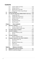
Appendix summary A A.1 DSEB-D16/SAS model block diagram A-1 A.2 DSEB-D16 model block diagram A-2 ASUS DSEB-D16 Series - Asus DSEB-D16 SAS | DSEB-D16 User's Manual for English Edition - Page 199
PCIE2 PCIX4 x8 PCI-X 133/100 8 x SAS LSI1068 H/W RAID 0, 1, 1E H/W RAID (5 ZCR) 82563 (Gilgal) Kumeran 1600 FSB 5400MCH (Seaburg) ESI x8 FBD800 FBDx4 FBDx4 FBDx4 FBDx4 6321ESB (ESB2) x1 x1 PCI 33 82573L 82573L Z9s 1 x IDE 6 x SATA Intel MSM (RAID 0, 1, 10, 5) ASUS DSEB-D16 Series A-1 - Asus DSEB-D16 SAS | DSEB-D16 User's Manual for English Edition - Page 200
A.2 DSEB-D16 model block diagram Intel® Dual-Core™ Xeon 5000/ 5100/ 5200/ 5300/ 5400 X16 slot PCIE1 X16 slot PCIE3 X16 gen2 X16 gen2 PCIE2 PCIX4 x8
-
 1
1 -
 2
2 -
 3
3 -
 4
4 -
 5
5 -
 6
6 -
 7
7 -
8
-
9
-
10
-
11
-
12
-
13
-
14
-
15
-
16
-
17
-
18
-
19
-
20
-
21
-
22
-
23
-
24
-
25
-
26
-
27
-
28
-
29
-
30
-
31
-
32
-
33
-
34
-
35
-
36
-
37
-
38
-
39
-
40
-
41
-
42
-
43
-
44
-
45
-
46
-
47
-
48
-
49
-
50
-
51
-
52
-
53
-
54
-
55
-
56
-
57
-
58
-
59
-
60
-
61
-
62
-
63
-
64
-
65
-
66
-
67
-
68
-
69
-
70
-
71
-
72
-
73
-
74
-
75
-
76
-
77
-
78
-
79
-
80
-
81
-
82
-
83
-
84
-
85
-
86
-
87
-
88
-
89
-
90
-
91
-
92
-
93
-
94
-
95
-
96
-
97
-
98
-
99
-
100
-
101
-
102
-
103
-
104
-
105
-
106
-
107
-
108
-
109
-
110
-
111
-
112
-
113
-
114
-
115
-
116
-
117
-
118
-
119
-
120
-
121
-
122
-
123
-
124
-
125
-
126
-
127
-
128
-
129
-
130
-
131
-
132
-
133
-
134
-
135
-
136
-
137
-
138
-
139
-
140
-
141
-
142
-
143
-
144
-
145
-
146
-
147
-
148
-
149
-
150
-
151
-
152
-
153
-
154
-
155
-
156
-
157
-
158
-
159
-
160
-
161
-
162
-
163
-
164
-
165
-
166
-
167
-
168
-
169
-
170
-
171
-
172
-
173
-
174
-
175
-
176
-
177
-
178
-
179
-
180
-
181
-
182
-
183
-
184
-
185
-
186
-
187
-
188
-
189
-
190
-
191
-
192
-
193
-
194
-
195
-
196
-
197
-
198
-
199
-
200
 |
 |

Motherboard
DSEB-D16
Series
DSEB-D16
DSEB-D16/SAS