Asus F2A85-V F2A85-V User's Manual - Page 42
F2A85-V USB3.0 Front panel connector
 |
View all Asus F2A85-V manuals
Add to My Manuals
Save this manual to your list of manuals |
Page 42 highlights
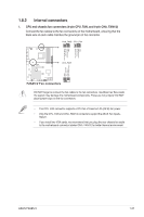
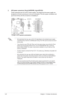
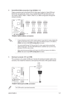
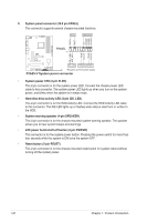
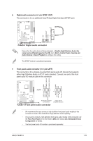
8. USB 2.0 connectors (10-1 pin USB56, USB78, USB910) These connectors are for USB 2.0 ports. Connect the USB module cable to any of these connectors, then install the module to a slot opening at the back of the system chassis. These USB connectors comply with USB 2.0 specification that supports up to 480Mbps connection speed. USB+5V USB_P10USB_P10+ GND NC USB+5V USB_P8USB_P8+ GND NC USB+5V USB_P6USB_P6+ GND NC F2A85-V USB910 USB78 USB56 PIN 1 PIN 1 PIN 1 USB+5V USB_P9USB_P9+ GND USB+5V USB_P7USB_P7+ GND USB+5V USB_P5USB_P5+ GND F2A85-V USB2.0 connectors Never connect a 1394 cable to the USB connectors. Doing so will damage the motherboard! The USB 2.0 module is purchased separately. 9. USB 3.0 connector (20-1 pin USB3_34) This connector is for the additional USB 3.0 ports, and complies with the USB 3.0 specificaton that supports up to 4.8Gbps connection speed. If the USB 3.0 front panel cable is available from your system chassis, with this USB 3.0 connector, you can have a front panel USB 3.0 solution. USB3_34 F2A85-V ID IntA_P1_D+ IntA_P1_D- GND IntA_P1_SSTX+ GND IntA_P1_SSTXIntA_P1_SSRX+ IntA_P1_SSRX- Vbus PIN 1 IntA_P2_D+ IntA_P2_DGND IntA_P2_SSTX+ IntA_P2_SSTXGND IntA_P2_SSRX+ IntA_P2_SSRXVbus F2A85-V USB3.0 Front panel connector You can connect the ASUS front panel USB 3.0 bracket to this connector to obtain the front panel USB 3.0 solution. 1-30 Chapter 1: Product introduction
-
 1
1 -
2
-
3
-
4
-
5
-
6
-
7
-
8
-
9
-
10
-
11
-
12
-
13
-
14
-
15
-
16
-
17
-
18
-
19
-
20
-
21
-
22
-
23
-
24
-
25
-
26
-
27
-
28
-
29
-
30
-
31
-
32
-
33
-
34
-
35
-
36
-
 37
37 -
 38
38 -
 39
39 -
 40
40 -
 41
41 -
 42
42 -
 43
43 -
 44
44 -
 45
45 -
 46
46 -
 47
47 -
48
-
49
-
50
-
51
-
52
-
53
-
54
-
55
-
56
-
57
-
58
-
59
-
60
-
61
-
62
-
63
-
64
-
65
-
66
-
67
-
68
-
69
-
70
-
71
-
72
-
73
-
74
-
75
-
76
-
77
-
78
-
79
-
80
-
81
-
82
 |
 |
