Asus F2F F2JFH User''s Manual for English Edtion(E2599) - Page 16
Front Side - bluetooth
 |
View all Asus F2F manuals
Add to My Manuals
Save this manual to your list of manuals |
Page 16 highlights
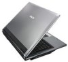
2 Knowing the Parts Front Side Refer to the diagram below to identify the components on this side of the Notebook PC. 1 OFF ON 234 5 6 1 Display Panel Latch One spring-loaded latch on the front of the Notebook PC locks the display panel in the closed position when the Notebook PC is not in use. To open the display panel, negotiate the latch with your thumb and lift up the display panel while holding the latch. Slowly tilt the display panel forward or backward to a comfortable viewing angle. WARNING! When opening, do not force the display panel down to the table or else the hinges may break! Never lift the Notebook PC by the display panel! 2 SPDIF Output Jack Combo This jack provides connection to SPDIF (Sony/Philips Digital Interface) compliant devices for digital audio output. Use this feature to turn the Notebook PC into a hi-fi home enter- tainment system. Headphone Output Jack The stereo headphone jack (1/8 inch) is used to connect the Notebook PC's audio out signal to amplified speakers or headphones. Using this jack automatically disables the built-in speakers. 3 Microphone Input Jack The mono microphone jack (1/8 inch) can be used to connect an external microphone or output signals from audio devices. Using this jack automatically disables the built-in microphone. Use this feature for video conferencing, voice narrations, or simple audio recordings. 4 Wireless Switch Enables or disables the built-in wireless LAN and Bluetooth (selected models). When enabled, the wireless status indicator will light. Windows software settings are necessary before use. 5 Status Indicators (front) Status indicator details are described in section 3. 16
-
 1
1 -
2
-
3
-
4
-
5
-
6
-
7
-
8
-
9
-
10
-
 11
11 -
 12
12 -
 13
13 -
 14
14 -
 15
15 -
 16
16 -
 17
17 -
 18
18 -
 19
19 -
 20
20 -
 21
21 -
22
-
23
-
24
-
25
-
26
-
27
-
28
-
29
-
30
-
31
-
32
-
33
-
34
-
35
-
36
-
37
-
38
-
39
-
40
-
41
-
42
-
43
-
44
-
45
-
46
-
47
-
48
-
49
-
50
-
51
-
52
-
53
-
54
-
55
-
56
-
57
-
58
-
59
-
60
-
61
-
62
-
63
-
64
-
65
-
66
-
67
-
68
-
69
-
70
-
71
-
72
-
73
-
74
-
75
-
76
-
77
-
78
-
79
-
80
-
81
-
82
-
83
-
84
-
85
-
86
-
87
-
88
-
89
 |
 |
