Asus H310A-EM-A User Manual English - Page 11
Motherboard information
 |
View all Asus H310A-EM-A manuals
Add to My Manuals
Save this manual to your list of manuals |
Page 11 highlights
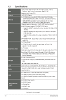
Connectors/Jumpers/Slots 1. COM1 Ring/+5V/+12V Selection jumpers (6-pin COM1_ESL, COM2_ESL) 2. ATX Power connectors (24-pin EATXPWR, 4-pin ATX12V) 3. CPU and Chassis Fan headers (4-pin CPU_FAN, 4-pin CHA_FAN) 4. Intel® LGA1151 CPU socket 5. M.2 socket 3 6. DDR4 DIMM slots 7. Serial ATA 6.0Gb/s connectors (7-pin SATA6G_1~4) 8. USB 2.0 connectors (USB7, USB8, USB914) 9. TPM connector (14-1 pin TPM) 10. Speaker header (4-pin SPEAKER) 11. System Panel header (10-1 pin F_PANEL) 12. Clear RTC RAM (2-pin CLRTC) 13. Serial port headers (10-1 pin COM3, COM4, COM5, COM6) 14. COM Debug header 15. LPT header 16. PS/2 Keyboard & Mouse header 17. Front Panel Audio header (10-1 pin AAFP) 18. Chassis Intrude headder 19. PCI slots 20. General purpose input/output connector (GPIO_CON) 21. PCI Express x4 slots 22. PCI Express x16 slot Page 2-12 2-24 2-18 2-4 2-21 2-9 2-20 2-17 2-18 2-20 2-19 2-11 2-22 2-21 2-16 2-22 2-23 2-13 2-26 2-16 2-25 2-25 Chapter 2: Motherboard information 2-3
-
 1
1 -
2
-
3
-
4
-
5
-
 6
6 -
 7
7 -
 8
8 -
 9
9 -
 10
10 -
 11
11 -
 12
12 -
 13
13 -
 14
14 -
 15
15 -
 16
16 -
17
-
18
-
19
-
20
-
21
-
22
-
23
-
24
-
25
-
26
-
27
-
28
-
29
-
30
-
31
-
32
-
33
-
34
-
35
-
36
-
37
-
38
-
39
-
40
-
41
-
42
-
43
-
44
-
45
-
46
-
47
-
48
-
49
-
50
-
51
-
52
-
53
-
54
-
55
-
56
-
57
-
58
-
59
-
60
-
61
-
62
-
63
-
64
-
65
-
66
-
67
-
68
-
69
-
70
-
71
-
72
-
73
-
74
-
75
-
76
-
77
 |
 |
