Asus KCMR-D12 User Guide
Asus KCMR-D12 Manual
 |
View all Asus KCMR-D12 manuals
Add to My Manuals
Save this manual to your list of manuals |
Asus KCMR-D12 manual content summary:
- Asus KCMR-D12 | User Guide - Page 1
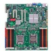
KCMR-D12 Motherboard - Asus KCMR-D12 | User Guide - Page 2
Product warranty or service will not be extended if: (1) the product is repaired, modified or altered, unless such repair, modification of alteration is authorized in writing by ASUS; or (2) the serial number of the product is defaced or missing. ASUS PROVIDES THIS MANUAL "AS IS" WITHOUT WARRANTY - Asus KCMR-D12 | User Guide - Page 3
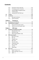
viii About this guide ix Typography x KCMR-D12 specifications summary xi Chapter 1: Product introduction 1.1 Welcome 1-3 1.2 Package contents 1-3 1.3 Serial number label 1-4 1.4 Special features 1-4 1.4.1 Product highlights 1-4 1.4.2 Innovative ASUS features 1-6 Chapter 2: Hardware - Asus KCMR-D12 | User Guide - Page 4
x8 slots (x8/x4 link 2-22 2.5.6 PCI Express x16 slot (x16/x8 link 2-22 2.5.8 Installing ASMB4 management board 2-23 2.5.9 Installing i Button 2-23 2.5.10 Installing ASUS PIKE RAID card 2-24 2.6 Jumpers 2-25 2.7 Connectors 2-29 2.7.1 Rear panel connectors 2-29 2.7.2 Internal connectors 2-30 - Asus KCMR-D12 | User Guide - Page 5
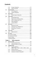
4-15 4.4.2 Chipset Configuration 4-18 4.5 Server menu 4-27 4.5.1 Remote Access Configuration Video on S3 Resume [No 4-29 4.6.3 ACPI 2.0 Support [ACPI v2.0 4-29 4.6.5 APM Configuration 4-30 4.6.6 4-34 4.7.4 Security 4-35 4.8 Tools menu 4-37 4.8.1 ASUS EZ Flash 2 4-37 4.9 Exit menu 4-38 Exit - Asus KCMR-D12 | User Guide - Page 6
6-3 6.1.2 Installing the RAID controller driver 6-5 6.2 AMD Processor Driver installation 6-15 6.3 LAN driver installation support DVD 6-27 6.6.2 Drivers menu 6-27 6.6.3 Utilities menu 6-28 6.6.4 Make disk menu 6-28 6.6.5 Contact information 6-28 Appendix: Reference information A.1 KCMR-D12 - Asus KCMR-D12 | User Guide - Page 7
that may cause undesired operation. This equipment has been tested and found to comply with the limits for a Class and used in accordance with manufacturer' s instructions, may cause harmful interference to radio communications. ASUS REACH website at http://csr.asus.com/english/REACH.htm. vii - Asus KCMR-D12 | User Guide - Page 8
qualified service technician or your retailer. Operation safety • Before installing the motherboard and adding devices on it, carefully read all the manuals stable surface. • If you encounter technical problems with the product, contact a qualified service technician or your retailer. This symbol of - Asus KCMR-D12 | User Guide - Page 9
motherboard. How this guide is organized This user guide contains the following parts: • Chapter 1: Product introduction This chapter describes the features of the motherboard and the new technologies it supports 5: RAID configuration This chapter provides instructions for setting up, creating, and - Asus KCMR-D12 | User Guide - Page 10
of the following symbols used throughout this manual. DANGER/WARNING: Information to prevent injury to yourself when trying to complete a task. CAUTION: Information to prevent damage to the components when trying to complete a task. IMPORTANT: Instructions that you MUST follow to complete - Asus KCMR-D12 | User Guide - Page 11
specifications summary Model Name Processor Support / System Bus Core Logic KCMR-D12 2 * socket C32 (LGA 1207) 4/6 Core AMD Opteron™ 4100 series HyperTransport™ Technology 3.0 6.4 GT/s per link (dual link) AMD SR5670 / AMD SP5100 Form Factor 12" x 13" ASUS Features Fan Speed V Control Rack - Asus KCMR-D12 | User Guide - Page 12
KCMR-D12 specifications summary Onboard I/O Connectors PSU Connector 24-pin SSI power KB/Mouse 1 Management Solution Software ASWM Monitoring Out of Band Remote Management CPU Temperature Optional ASMB4-iKVM for KVM-over-IP support V FAN RPM V Environment Operation temperature: 10℃-35℃ - Asus KCMR-D12 | User Guide - Page 13
This chapter describes the motherboard introPdruoc1dtuiocnt features and the new technologies it supports. - Asus KCMR-D12 | User Guide - Page 14
Chapter summary 1 1.1 Welcome 1-3 1.2 Package contents 1-3 1.3 Serial number label 1-4 1.4 Special features 1-4 ASUS KCMR-D12 - Asus KCMR-D12 | User Guide - Page 15
Thermal sensor Standard Gift Box Pack 6 1 Accessory I/O Shield Application CD Support CD Documentation User Guide Packing Qty. 1 1 1 1pc per carton Standard Bulk Pack -- -- 1 1 1 10pcs per carton If any of the above items is damaged or missing, contact your retailer. ASUS KCMR-D12 1-3 - Asus KCMR-D12 | User Guide - Page 16
serial number of the product, ASUS Technical Support team members can then offer a quicker and satisfying solution to your problems. KCMR-D12 xxS2xxxxxxxxx Made in China 合格 1.4 Special features 1.4.1 Product highlights Latest processor technology The motherboard comes with dual 1207-pin surface - Asus KCMR-D12 | User Guide - Page 17
throughput close to Gigabit bandwidth. Serial ATA II technology The motherboard supports the Serial ATA II 3 Gb/s technology through the Serial ATA This motherboard uses all high-quality conductive polymer capacitors for durability, improved lifespan, and enhanced thermal capacity. ASUS KCMR-D12 - Asus KCMR-D12 | User Guide - Page 18
efficient operation. PIKE (Proprietary I/O Kit Expansion) PIKE is an on-demand upgrade kit for users. This ASUS unique feature enables users to choose their preferred I/O solutions. ASUS provides multiple SAS solutions for different segments and purposes and PIKE saves lots of validation efforts and - Asus KCMR-D12 | User Guide - Page 19
This chapter lists the hardware setup procedures that you have to perform when installing system components. It includes description of the jumpers and connectors on the motherboard. 2 Hardware information - Asus KCMR-D12 | User Guide - Page 20
Chapter summary 2 2.1 Before you proceed 2-3 2.2 Motherboard overview 2-6 2.3 Central Processing Unit (CPU 2-10 2.4 System memory 2-17 2.5 Expansion slots 2-20 2.6 Jumpers 2-25 2.7 Connectors 2-29 ASUS KCMR-D12 - Asus KCMR-D12 | User Guide - Page 21
in soft-off mode. This is a reminder that you should shut down the system and unplug the power cable before removing or plugging in any motherboard component. The illustration below shows the location of the onboard LED. ASUS KCMR-D12 2-3 - Asus KCMR-D12 | User Guide - Page 22
2. CPU warning LED (ERR_CPU1, ERR_CPU2) The CPU warning LEDs light up to indicate that an impending failure of the corresponding CPU. 3. DIMM warning LED (ERR_DIMMA1/2/3; ERR_DIMMB1/2/3; ERR_DIMMC1/2/3; ERR_DIMMD1/2/3) The DIMM warning LEDs light up to indicate that an impending failure of the - Asus KCMR-D12 | User Guide - Page 23
LED (BMC_LED1) The green heartbeat LED blinks per second to indicate that the ASMB4 is working normally. • The heartbeat LED functions only when you install the ASUS ASMB4. • Everytime after the AC power is replugged, you have to wait for about 30 seconds for the system power up ASUS KCMR-D12 2-5 - Asus KCMR-D12 | User Guide - Page 24
. Ensure to unplug the chassis power cord before installing or removing the motherboard. Failure to do so can cause you physical injury and damage motherboard components! 2.2.1 Placement direction When installing the motherboard, ensure that you place it into the chassis in the correct orientation - Asus KCMR-D12 | User Guide - Page 25
2.2.4 Motherboard layouts ASUS KCMR-D12 2-7 - Asus KCMR-D12 | User Guide - Page 26
16 slot (x16/x8 link) 6. PIKE slot Jumpers 1. Clear RTC RAM (CLRTC1) 2. VGA controller setting (3-pin VGA_SW1)) 3. DDR3 voltage control Rear panel connectors 1. PS/2 mouse port (green) 2. RJ-45 port for iKVM 3. PS/2 keyboard port (purple) 4. USB 2.0 ports 1 and 2 5. Serial - Asus KCMR-D12 | User Guide - Page 27
. System panel connector (20-pin PANEL1) 11. Auxiliary panel connector (20-2 pin AUX_PANEL1) Page 2-30 2-31 2-31 2-32 2-32 2-33 2-33 2-34 2-34 2-35 2-36 ASUS KCMR-D12 2-9 - Asus KCMR-D12 | User Guide - Page 28
Socket designed for the AMD Opteron™ 4100 series CPU in the Land Grid Array (LGA) package. • Upon purchase of the motherboard, ensure that the PnP the cap after installing the motherboard. ASUS will process Return Merchandise Authorization (RMA) requests only if the motherboard comes with the cap on - Asus KCMR-D12 | User Guide - Page 29
force the CPU into the socket to prevent bending the connectors on the socket and damaging the CPU! CPU notch Alignment key Gold triangle mark ASUS KCMR-D12 2-11 - Asus KCMR-D12 | User Guide - Page 30
7. Apply some Thermal Interface Material to the exposed area of the CPU that the heatsink will be in contact with, ensuring that it is spread in an even thin layer. Some heatsinks come with pre-applied Thermal Interface Material. If so, skip this step. The Thermal Interface Material is toxic. DO NOT - Asus KCMR-D12 | User Guide - Page 31
installing the CPU or installing other motherboard components. • Ensure that you use only AMD-certified heatsink and fan assembly. instructions for the CPU, heatsink, and the retention mechanism. If the instructions in this section do not match the CPU documentation, follow the latter. ASUS KCMR-D12 - Asus KCMR-D12 | User Guide - Page 32
2. Attach one end of the retention bracket to the retention module base. 3. Align the other end of the retention bracket (near the retention bracket lock) to the retention module base. A clicking sound denotes that the retention bracket is in place. Ensure that the fan and heatsink assembly - Asus KCMR-D12 | User Guide - Page 33
5. Connect the CPU fan cable to the corresponding connector on the motherboard. • Do not forget to connect the CPU fan connector! Hardware monitoring errors can occur if you fail to plug this connector. • This connector is backward compatible with old 3-pin CPU fan. ASUS KCMR-D12 2-15 - Asus KCMR-D12 | User Guide - Page 34
2.3.3 Installing the CPU heatsink The AMD Opteron™ 4100 series processors require a specially designed heatsink to ensure optimum thermal condition and performance. • Ensure to use qualified heatsink assembly only. • Ensure that you - Asus KCMR-D12 | User Guide - Page 35
2.4 System memory 2.4.1 Overview The motherboard comes with twelve (12) Double Data Rate 3 (DDR3) Dual Inline Memory Modules (DIMM) sockets. A DDR3 module has the same physical dimensions as a DDR2 power consumption. The figure illustrates the location of the DDR3 DIMM sockets: ASUS KCMR-D12 2-17 - Asus KCMR-D12 | User Guide - Page 36
optimum compatibility, it is recommended that you obtain memory modules from the same vendor. Memory population table SR: Single Rank; DR: 1T 1T 1T 2T 2T 2T 2T DO NOT install DIMMs of different voltages on the motherboard at the same time, such as a combination of 1.5V DIMMs and 1.35V LVDIMMs. - Asus KCMR-D12 | User Guide - Page 37
do so can cause severe damage to both the motherboard and the components. To install a DIMM: 2 Support the DIMM lightly with 1 1 your fingers when pressing the retaining clips. The DIMM might get damaged when it flips out with extra force. 2. Remove the DIMM from the socket. ASUS KCMR-D12 - Asus KCMR-D12 | User Guide - Page 38
sub‑sections describe the slots and the expansion cards that they support. Ensure to unplug the power cord before adding or removing expansion cards. Failure to do so may cause you physical injury and damage motherboard components. 2.5.1 Installing an expansion card To install an expansion card - Asus KCMR-D12 | User Guide - Page 39
Mouse Port 13 8 Numeric Data Processor 14* 9 Primary IDE Channel 15* 10 Secondary IDE Channel * These IRQs are usually available for ISA or PCI devices. ASUS KCMR-D12 2-21 - Asus KCMR-D12 | User Guide - Page 40
slots provide x8/x4 link to CPU. These slots support VGA cards and various server class high performance add-on cards. 2.5.6 PCI server class high performance add-on cards. 2.5.7 PIKE slot The PIKE slot allows you to choose and change your preferred SAS solution easily. Install an optional ASUS - Asus KCMR-D12 | User Guide - Page 41
the BMC_FW1 header on the motherboard. 2. Orient and press the ASMB4 management board in place. 2.5.9 Installing i Button Follow the steps below to install an optional i Button on your motherboard. 1. Locate the i Button slot on the motherboard. 2. Snap the i Button in place. ASUS KCMR-D12 2-23 - Asus KCMR-D12 | User Guide - Page 42
RAID card Follow the steps below to install an optional ASUS RAID card on your motherboard. 1. Locate the PIKE RAID card slot on the motherboard. 2. Align the golden fingers of the RAID card with the PIKE RAID card slot. 3. Insert the RAID card into the PIKE RAID card slot. Make - Asus KCMR-D12 | User Guide - Page 43
RTC RAM, never remove the cap on CLRTC jumper default position. Removing the cap will cause system boot failure! If the steps above do not help, remove the onboard battery and move the jumper again to clear the CMOS RTC RAM data. After the CMOS clearance, reinstall the battery. ASUS KCMR-D12 2-25 - Asus KCMR-D12 | User Guide - Page 44
2. VGA controller setting (3-pin VGA_SW1) This jumper allows you to enable or disable the onboard VGA controller. Set to pins 1-2 to activate the VGA feature. 3. DDR3 voltage control setting (4-pin LVDDR3_SEL1; LVDDR3_SEL2) These jumpers allow you to adjust the DIMM voltage. Set to pins 1-2 to - Asus KCMR-D12 | User Guide - Page 45
fan but set the jumper for a 4-pin fan, the fan control will not work and the fan you installed will always run at full speed. ASUS KCMR-D12 2-27 - Asus KCMR-D12 | User Guide - Page 46
recover the BIOS settings when it becomes corrupted. To update the BIOS: 1. Prepare a USB flash disk that contains the original or latest BIOS for the motherboard (XXXXXX.ROM) and the AFUDOS.EXE utility. 2. Set the jumper to pins 2-3. 3. Insert the USB flash and turn on the system to update the BIOS - Asus KCMR-D12 | User Guide - Page 47
PS/2 mouse port (green). This port is for a PS/2 mouse. 2. RJ-45 port for iKVM. This RJ-45 port functions only when you install ASMB4 management card. 3 PS/2 keyboard port (purple). This port is for a PS/2 keyboard. 4. GREEN 1 Gbps connection ACT/LINK SPEED LED LED LAN port ASUS KCMR-D12 2-29 - Asus KCMR-D12 | User Guide - Page 48
2.7.2 Internal connectors 1. Serial ATA connectors (7-pin SATA1, SATA2, SATA3, SATA4; RED) (7-pin SATA5, SATA6; Black) Supported by the AMD® SP5100 chipset, these connectors are for the Serial ATA signal cables for Serial ATA hard disk drives that allows up to 3Gb/s of data transfer - Asus KCMR-D12 | User Guide - Page 49
SAS) and Serial ATA (SATA). Each connector supports one device. These SAS connectors function only when you install a PIKE RAID card to the motherboard. 3. USB connector (10-1 pin USB34, connectors comply with USB 2.0 specification that supports up to 480 Mbps connection speed. ASUS KCMR-D12 2-31 - Asus KCMR-D12 | User Guide - Page 50
support cooling fans of 350 mA-740 mA (8.88 W max.) or a total of 3.15 A-6.66 A (53.28 W max.) at +12V. Connect the fan cables to the fan connectors on the motherboard motherboard components. • These are not jumpers! DO NOT place jumper caps on the fan connectors! • All fans feature the ASUS Smart - Asus KCMR-D12 | User Guide - Page 51
an ASUS® Server Management Board 4 Series (ASMB4). 7. Thermal sensor cable connectors (3-pin TR1, TR2) These connectors are for temperature monitoring. Connect the thermal sensor cables to these connectors and place the other ends to the devices, which you want to monitor temperature. ASUS KCMR-D12 - Asus KCMR-D12 | User Guide - Page 52
if you intend to install additional devices. 9. Location LED cable connector (3-pin LOCLED1) This connector is for a LED cable that allows you to know the server location. 2-34 Chapter 2: Hardware information - Asus KCMR-D12 | User Guide - Page 53
10. System panel connector (20-pin PANEL1) This connector supports several chassis-mounted functions. 1. System power LED (3-pin PLED) This 3-pin connector is for the 2-pin connector is for the chassis-mounted reset button for system reboot without turning off the system power. ASUS KCMR-D12 2-35 - Asus KCMR-D12 | User Guide - Page 54
11. Auxiliary panel connector (20-pin AUX_PANEL1) This connector is for additional front panel features including front panel SMB, locator LED and switch, chassis intrusion, and LAN LEDs. 1. Front panel SMB (6-1 pin FPSMB) These leads connect the front panel SMBus cable. 2. LAN activity LED (2-pin - Asus KCMR-D12 | User Guide - Page 55
This chapter describes the power up sequence, and ways of shutting down the system. 3 Powering up - Asus KCMR-D12 | User Guide - Page 56
Chapter summary 3 3.1 Starting up for the first time 3-3 3.2 Turning off the computer 3-4 ASUS KCMR-D12 - Asus KCMR-D12 | User Guide - Page 57
30 seconds from the time you turned on the power, the system may have failed a power-on test. Check the jumper settings and connections or call your retailer for assistance. 7. At power on, hold down the key to enter the BIOS Setup. Follow the instructions in Chapter 4. ASUS KCMR-D12 3-3 - Asus KCMR-D12 | User Guide - Page 58
3.2 Powering off the computer 3.2.1 Using the OS shut down function If you are using Windows® 2000/2003 Server: 1. Click Start then click Shut Down. 2. Select Shut Down from the What do you want the computer to do? list box. 3. Select Shutdown Event Tracker. 4. - Asus KCMR-D12 | User Guide - Page 59
This chapter tells how to change the system settings through the BIOS Setup menus. Detailed descriptions of the BIOS parameters are also provided. 4 BIOS setup - Asus KCMR-D12 | User Guide - Page 60
Chapter summary 4 4.1 Managing and updating your BIOS 4-3 4.2 BIOS setup program 4-7 4.3 Main menu 4-10 4.4 Advanced menu 4-15 4.5 Server menu 4-27 4.6 Power menu 4-29 4.7 Boot menu 4-33 4.8 Tools menu 4-37 4.9 Exit menu 4-38 ASUS KCMR-D12 - Asus KCMR-D12 | User Guide - Page 61
the future. Copy the original motherboard BIOS using the BUPDATER utility. 4.1.1 ASUS EZ Flash 2 utility The ASUS EZ Flash 2 feature allows Flash 2 BIOS ROM Utility V4.16 FLASH TYPE: MXIC 25L1605A Current ROM BOARD: KCMR-D12 VER: 0301 DATE: 10/08/2010 Update ROM BOARD: VER: DATE: PATH: A:\ - Asus KCMR-D12 | User Guide - Page 62
BUPDATER utility: 1. Visit the ASUS website at www.asus.com and download the latest BIOS file for the motherboard. Save the BIOS file to a bootable�U��S��B��fl�a�s�h��d�i�s�k��d�r�iv��e��. 2. Copy the BUPDATER utility (BUPDATER.exe) from the ASUS support website at support.asus.com to the bootable - Asus KCMR-D12 | User Guide - Page 63
BIOS file. ASUSTek BIOS Update for DOS V1.06 (09/08/04) FLASH TYPE: MXIC 25L1605A Current ROM BOARD: KCMR-D12 VER: 0301 DATE: 10/08/2010 Update ROM BOARD: VER: DATE: PATH: WARNING! Do not turn off disk drive. The BIOS update is finished! Please restart your system. C:\> ASUS KCMR-D12 4-5 - Asus KCMR-D12 | User Guide - Page 64
that contains the updated BIOS file. Prepare a USB flash drive containing the updated motherboard BIOS before using this utility. Recovering the BIOS from a USB flash drive To version for this motherboard. Visit the ASUS website at www.asus.com to download the latest BIOS file. 4-6 Chapter 4: - Asus KCMR-D12 | User Guide - Page 65
can recognize these changes and record them in the CMOS RAM of the firmware chip. The firmware chip on the motherboard stores the Setup utility. When you start up the your screen. • Visit the ASUS website at www.asus.com to download the latest BIOS file for this motherboard. ASUS KCMR-D12 4-7 - Asus KCMR-D12 | User Guide - Page 66
Power Boot Tools For changing the basic system configuration For changing the advanced system settings For changing the advanced server settings For changing the advanced power management (APM) configuration For changing the system boot configuration For configuring options for special - Asus KCMR-D12 | User Guide - Page 67
the screen. 4.2.9 General help Pop-up window Scroll bar At the top right corner of the menu screen is a brief description of the selected item. ASUS KCMR-D12 4-9 - Asus KCMR-D12 | User Guide - Page 68
menu screen items and how to navigate through them. Main Advanced BIOS SETUP UTILITY Server Power Boot Tools Exit System Time [13:44:30] System Date [Fri, 10 DMA :Ultra DMA-6 S.M.A.R.T.:Supported Disabled: Disabled LBA Mode. Auto: Enables LBA Mode if the device supports it and the device - Asus KCMR-D12 | User Guide - Page 69
the data transfer from and to the device occurs multiple sectors at a time if the device supports multi-sector transfer feature. When set to [Disabled], the data transfer from and to the ] Enables or disables 32-bit data transfer. Configuration options: [Disabled] [Enabled] ASUS KCMR-D12 4-11 - Asus KCMR-D12 | User Guide - Page 70
4.3.4 Storage Configuration The items in this menu allow you to set or change the configurations for the IDE/SATA devices installed in the system. Select an item then press if you wish to configure the item. Main BIOS SETUP UTILITY Storage Configuration OnChip SATA Channel [Enabled] - Asus KCMR-D12 | User Guide - Page 71
system memory. System Memory Information Displays system memory information. Main System Memory Information CPU1 Memory Information CPU2 Memory Information BIOS SETUP UTILITY CPU1/2 Memory Configuration Allows you to check information of installed memory (6 DIMMs per CPU). ASUS KCMR-D12 4-13 - Asus KCMR-D12 | User Guide - Page 72
CPU1/2 Memory Configuration Displays the auto-detected memory specification. Main CPU1 Memory Configuration Node0 Speed N/A DIMM_A1 N/A DIMM_A2 N/A DIMM_A3 N/A DIMM_B1 N/A DIMM_B2 N/A DIMM_B3 N/A BIOS SETUP UTILITY 4-14 Chapter 4: BIOS setup - Asus KCMR-D12 | User Guide - Page 73
Main Advanced BIOS SETUP UTILITY Server Power Boot Tools Exit CPU not appear if your CPU does not support the related functions. Advanced BIOS SETUP UTILITY :5.1104.1 Socket Count :1 Node Count :1 Core Count :6 AMD Opteron(tm) Processor 4122 Revision: D0 Cache L1: 512KB ASUS KCMR-D12 4-15 - Asus KCMR-D12 | User Guide - Page 74
Scroll down for more items. Advanced BIOS SETUP UTILITY CPU DownCore Mode C1E Support CPU2 [Auto Mode] [Enabled] [Enabled] Cold Reset is needed after changing option. +F1 F10 ESC Select Screen Select Item Change Option General Help Save and - Asus KCMR-D12 | User Guide - Page 75
Level] [No Leveling] [2 Cores] [4 Cores] C1E Support [Enabled] Allows you to enable or disable Enhanced Halt State support. Configuration options: [Disabled] [Enabled] CPU2 [Enabled] Allows you to enable or disable the CPU2 function. Configuration options: [Disabled] [Enabled] ASUS KCMR-D12 4-17 - Asus KCMR-D12 | User Guide - Page 76
item then press to display the sub-menu. Advanced Advanced Chipset Settings BIOS SETUP UTILITY Options for NB NorthBridge Configuration SouthBridge Configuration SR5670 Configuration ←→ Select Screen ↑↓ Select Item Enter Go to Sub Screen F1 General Help F10 Save and Exit ESC Exit v02.61 - Asus KCMR-D12 | User Guide - Page 77
Megatrends, Inc. Rank Interleaving [Auto] Allows you to set the rank memory interleaving setting. Configuation options: [Disabled] [Auto] Node Interleaving [Disabled] Allows you Allows you to enable or disable channel B, C and D. Configuation options: [Disabled] [Enabled] ASUS KCMR-D12 4-19 - Asus KCMR-D12 | User Guide - Page 78
mode dynamically sets the DRAM scrub rate so all of memory is scrubbed in 8 hours. +F1 F10 ESC Select ] [20.97ms] [42.00ms] [84.00ms] Data Cache BG Scrub [Disabled] Allows the L1 Data Cache ram to be corrected while idle. Configuration options: [Disabled] [40ns] [80ns] [160ns] [320ns] [640ns] - Asus KCMR-D12 | User Guide - Page 79
Disabled] Allows the L3 Data Cache ram to be corrected while idle. Manual] Memory Clock Speed [400 MHz] Allows you to set the memory clock frequency. This item available only when you set DRAM Timing Config to [Manual]. Configuration options: [333 MHz] [400 MHz] [533 MHz] [667 MHz] ASUS KCMR-D12 - Asus KCMR-D12 | User Guide - Page 80
SouthBridge Configuration Advanced BIOS SETUP UTILITY SouthBridge Chipset Configuration SP5100 CIMx Version : 5.6.0 SB Azalia Audio Configuration SB Debug Configuration Options for SB HD Azalia OHCI HC (Bus 0 Dev 18 Fn 0) OHCI HC (Bus 0 Dev 18 Fn 1) EHCI HC (Bus 0 Dev 18 Fn 2) OHCI HC (Bus 0 - Asus KCMR-D12 | User Guide - Page 81
set to [Enabled], the clocks for unused SATA ports in IDE will be shut down and the system saves some power. Configuration options: [Disabled] [Enabled] ASUS KCMR-D12 4-23 - Asus KCMR-D12 | User Guide - Page 82
0 Dev 19 Fn 1); EHCI HC (Bus 0 Dev 19 Fn 2); OHCI HC (Bus 0 Dev 20 Fn 5) [Enabled] Configuraiton options: [Disabled] [Enabled] SR5670 Configuration Advanced BIOS SETUP UTILITY SR5650 Configuration PCI Express Configuration Hyper Transport Configuration IOMMU [Disabled] VGA ROM Boot Priority - Asus KCMR-D12 | User Guide - Page 83
[L1] Configuration options: [Disabled] [L1] NP NB-SB VC1 Traffic Support [Disabled] Configuration options: [Disabled] [Enabled] Compliance Mode [Disabled] Configuration UnitID Clumping [Auto] Configuration options: [Auto] [Disabled] [UnitID 2/3] [UnitID B/C] [UnitID 2/3&B/C] ASUS KCMR-D12 4-25 - Asus KCMR-D12 | User Guide - Page 84
Priority [PCIE VGA Card] Allows you to set the VGA ROM boot priority. Configuration options: [PCIE VGA Card] [Onboard VGA] Debug Option Memory Decode on Sec. GFX [Disabled] Configuration options: [Disabled] [Force] IOC Peer-to-Peer Mode [Auto] Configuration options: [Auto] [Default] [Mode 1] [Mode - Asus KCMR-D12 | User Guide - Page 85
Access features. Select an item then press to display the configuration options. Server BIOS SETUP UTILITY Configure Remote Access type and parameters Remote Access [Enabled] Serial port ] The following items appear only when Remote Access is set to [Enabled]. ASUS KCMR-D12 4-27 - Asus KCMR-D12 | User Guide - Page 86
. Configuration options: [None] [Hardware] [Software] Redirection After BIOS POST [Disabled] Sets the redirection mode after the BIOS Power-On Self-Test (POST). Some operating system may not work when set to [Always]. Configuration options: [Disabled] [Boot Loader] [Always] Terminal Type [VT - Asus KCMR-D12 | User Guide - Page 87
Server Suspend Mode Repost Video on S3 Resume ACPI 2.0 Support ACPI APIC support support in the Advanced Programmable Interrupt Controller (APIC). When set to [Enabled], the ACPI APIC table pointer is included in the RSDT pointer list. Configuration options: [Disabled] [Enabled] ASUS KCMR-D12 - Asus KCMR-D12 | User Guide - Page 88
4.6.5 APM Configuration BIOS SETUP UTILITY Power Power On Configuration Restore on AC Power Loss [Last State] Resume On PCIE Wake# [Disabled] Resume On Ring [Disabled] Resume On RTC Alarm [Disabled] Options Power On Power Off Last State ←→ Select Screen ↑↓ Select Item +- Change Option - Asus KCMR-D12 | User Guide - Page 89
Copyright 1985-2010, American Megatrends, Inc. CPU1/CPU2/TR1/TR2 Temperature [xxxºC/xxxºF] The onboard hardware monitor automatically detects and displays the motherboard component and CPU temperatures. Select [Ignored] if you do not wish to display the detected temperatures. ASUS KCMR-D12 4-31 - Asus KCMR-D12 | User Guide - Page 90
fans, and rear fans in rotations per minute (RPM). If the fan is not connected to the motherboard, the field shows [N/A]. Fan Speed Control [Generic Mode] Allows you to configure the ASUS Smart Fan feature that smartly adjusts the fan speeds for more efficient system operation. Configuration options - Asus KCMR-D12 | User Guide - Page 91
options. Select an item then press to display the sub-menu. Main Advanced Server Boot Settings Boot Device Priority BIOS SETUP UTILITY Power Boot Tools Boot Settings Configuration Security Exit boot priority sequence of the hard disk drives or the optical drives. ASUS KCMR-D12 4-33 - Asus KCMR-D12 | User Guide - Page 92
[Enabled] Enabling this item allows the BIOS to skip some power on self tests (POST) while booting to decrease the time needed to boot the system. When options: [Disabled] [Enabled] Set this item to [Enabled] to use the ASUS MyLogo2™ feature. AddOn ROM Display Mode [Force BIOS] Allows you to set the - Asus KCMR-D12 | User Guide - Page 93
press . The message "Password Uninstalled" appears. If you forget your BIOS password, you can clear it by erasing the CMOS Real Time Clock (RTC) RAM. See section 2.6 Jumper for information on how to erase the RTC RAM. ASUS KCMR-D12 4-35 - Asus KCMR-D12 | User Guide - Page 94
set a supervisor password, the other items appear to allow you to change other security settings. Main Advanced BIOS SETUP UTILITY Server Power Boot Tools Exit Supervisor Password : Installed User Password : Not Installed Change Supervisor Password User Access Level Change User Password - Asus KCMR-D12 | User Guide - Page 95
. Select an item then press to display the submenu. Main Advanced ASUS EZ Flash 2 Server BIOS SETUP UTILITY Power Boot Tools Exit Press ENTER to run the utility to select and update BIOS. This uitlity supports 1. FAT 12/16/32 (r/w) 2. NTFS (read only) 3. CD-DISC (read only) ←→ Select - Asus KCMR-D12 | User Guide - Page 96
and save or discard your changes to the BIOS items. Main Advanced Server BIOS SETUP UTILITY Boot Exit Exit Options Exit and Save Changes Exit and ensure the values you selected are saved to the CMOS RAM. An onboard backup battery sustains the CMOS RAM so it stays on even when the PC is turned - Asus KCMR-D12 | User Guide - Page 97
This chapter provides instructions for setting up, creating, and configuring RAID sets using the available utilities. 5RAID configuration - Asus KCMR-D12 | User Guide - Page 98
Chapter summary 5 5.1 Setting up RAID 5-3 5.2 FastBuild Utility 5-5 ASUS KCMR-D12 - Asus KCMR-D12 | User Guide - Page 99
or speed. If you want to boot the system from a hard disk drive included in a created RAID set, copy first the RAID driver from the support CD to a floppy disk before you install an operating system to the selected hard disk drive. ASUS KCMR-D12 5-3 - Asus KCMR-D12 | User Guide - Page 100
: 1. Install the SATA hard disks into the drive bays following the instructions in the system user guide. 2. Connect a SATA signal cable to the signal connector at the back of each drive and to the SATA connector on the motherboard. 3. Connect a SATA power cable to the power connector on each drive - Asus KCMR-D12 | User Guide - Page 101
RAID 5, SPAN and JBOD set(s) from Serial ATA hard disk drives that are connected to the Serial ATA connectors supported by the Promise RAID. To enter the FastBuild Utility: 1. Install all the Serial ATA hard disk drives at Red and may not exactly match the items on your screen. ASUS KCMR-D12 5-5 - Asus KCMR-D12 | User Guide - Page 102
5.2.1 Creating a RAID set (RAID 0, RAID 1, RAID 10, RAID 5, SPAN or JBOD) To create a RAID set: 1. From the main control panel, press to to enter the LD View Menu. FastBuild (tm) Utility (c) 2004-2010 Promise Technology, Inc. [ Main Menu ] View Drive Assignment .......[ 1 ] LD View / LD Define - Asus KCMR-D12 | User Guide - Page 103
(GB) 250.05 250.05 250.05 250.05 Assignment N N N N [ Keys Available ] [↑] Up [↓] Down [PaUp/PaDn] Switch Page [Space] Change Option [Ctrl+Y] Save [ESC] Exit ASUS KCMR-D12 5-7 - Asus KCMR-D12 | User Guide - Page 104
4. After you have selected the desired RAID mode, use the down arrow key to select desired disks for the RAID set. FastBuild (tm) Utility (c) 2004-2010 Promise Technology, Inc. [ LD Define Menu ] LD No LD Name LD 1 Logical Drive 1 RAID Mode Drv RAID 1 1 Stripe Block Gigabyte Boundary Read - Asus KCMR-D12 | User Guide - Page 105
kSeAyTAto3Gignore this opt2i5o0n.>05 HDTXXXXXXXXXXXX SATA 3G 250.05 Assignment Y Y N N [ Keys Available ] [↑] Up [↓] Down [PaUp/PaDn] Switch Page [Space] Change Option [Ctrl+Y] Save [ESC] Exit ASUS KCMR-D12 5-9 - Asus KCMR-D12 | User Guide - Page 106
8. Press + to modify the disk array size or press any other key to use all the available capacity of the disk drive. FastBuild (tm) Utility (c) 2004-2010 Promise Technology, Inc. [ LD Define Menu ] LD No LD Name LD 1 Logical Drive 1 RAID Mode Drv RAID 1 2 Stripe Block Gigabyte - Asus KCMR-D12 | User Guide - Page 107
01:01 02:01 [ Drives Assignments ] Drive Model HDTXXXXXXXXXXXX HDTXXXXXXXXXXXX Capabilities SATA 3G SATA 3G Capacity(GB) 250.05 250.05 Any Key To Continue...... ASUS KCMR-D12 5-11 - Asus KCMR-D12 | User Guide - Page 108
5.2.2 Deleting a RAID set To delete a RAID set: 1. From the main control panel, press to to enter the Delete LD Menu. FastBuild (tm) Utility (c) 2004-2010 Promise Technology, Inc. [ Main Menu ] View Drive Assignment .......[ 1 ] LD View / LD Define Menu .....[ 2 ] Delete LD Menu 3 ] Controller - Asus KCMR-D12 | User Guide - Page 109
LD Menu ] < There is no any LD > [ Keys Available ] [↑] Up [↓] Down [PaUp/PaDn] Switch Page [Del/Alt+D] Delete LD [Ctrl+V] View JBOD Disk [ESC] Exit ASUS KCMR-D12 5-13 - Asus KCMR-D12 | User Guide - Page 110
5.2.3 Viewing the Drive Assignment To view the drive assignment: 1. From the main control panel, press to to enter the Drive Assignment Menu. FastBuild (tm) Utility (c) 2004-2010 Promise Technology, Inc. [ Main Menu ] View Drive Assignment .......[ 1 ] LD View / LD Define Menu .....[ 2 ] Delete - Asus KCMR-D12 | User Guide - Page 111
. [ Adapter Configuration - Options ] No Parameters Defined for Current Disk(s)... [ System Resources Configuration ] Controller IRQ: 10 AHCI HBA MMIO Base Address: FAFFE400 [ESC] Exit [ Keys Available ] ASUS KCMR-D12 5-15 - Asus KCMR-D12 | User Guide - Page 112
5-16 Chapter 5: RAID configuration - Asus KCMR-D12 | User Guide - Page 113
This chapter provides instructions for installing the necessary drivers for different system components. 6Driver installation - Asus KCMR-D12 | User Guide - Page 114
.e.r..in.s.t.a.l.la.t.io.n 6-15 6.3 LAN driver installation 6-19 6.4 ATI SM Bus controller driver installation 6-23 6.5 Display driver installation 6-24 6.6 Management application and utilities installation 6-27 ASUS KCMR-D12 - Asus KCMR-D12 | User Guide - Page 115
as the first boot priority to boot from the support DVD. Save your changes, and then exit the BIOS Setup. 4. Restart the computer. The Makedisk menu appears. Create Driver Diskette Menu Promise SW ROMB Controller Driver AMD AHCI Controller Driver Write DMI FreeDOS command prompt ASUS KCMR-D12 6-3 - Asus KCMR-D12 | User Guide - Page 116
enter the sub-menu. Promise SW ROMB Controller Driver Windows Server 2003 32/64 bit Windows Server 2008 32 bit Windows Server 2008 64 bit Windows Server 2008 R2 64 bit RHEL AS4 UP8 32 bit RHEL AS4 disk drive. 7. Press . 8. Follow screen instructions to create the driver disk. 6-4 Chapter 6: - Asus KCMR-D12 | User Guide - Page 117
have chosen to manually specify an adapter. Currently, Setup will load support for the support disks from a mass storage device manufacturer, or do not want to specify additional mass storage devices for use with Windows, press ENTER. S=Specify Additional Device ENTER=Continue F3=Exit ASUS KCMR-D12 - Asus KCMR-D12 | User Guide - Page 118
. Windows Setup Please insert the disk labeled Manufacturer-supplied hardware support disk into Drive A: * Press ENTER when ready. ENTER=Continue ESC screen instructions to continue. To an existing Windows® Server OS To install the RAID controller driver on an existing Windows® Server OS - Asus KCMR-D12 | User Guide - Page 119
Properties from the menu. 5. Click the Driver tab, and then click the Driver Details button to display the RAID controller drivers. 6. Click OK when finished. ASUS KCMR-D12 6-7 - Asus KCMR-D12 | User Guide - Page 120
Red Hat® Enterprise Linux OS 4.7/4.8 To install the RAID controller driver when installing�R��e�d�H��a�t® Enterprise OS: 1. Boot the system from the Red Hat® OS installation CD. 2. At the boot:, type linux dd. 3. Pr�e�s��s��. - To install or upgrade in graphical mode, press the - Asus KCMR-D12 | User Guide - Page 121
7. Select Skip and press to continue. CD Found To begin testing the CD media before installation press OK. Choose Skip to skip the media test and start the installation. OK Skip 8. Follow the onscreen instructions to finish installing the RedHat operating system. ASUS KCMR-D12 6-9 - Asus KCMR-D12 | User Guide - Page 122
Red Hat® Enterprise Linux OS 5.0 To install the RAID controller driver when installing�R��e�d�H��a�t® Enterprise OS: 1. Boot the system from the Red Hat® OS installation CD. 2. At the boot:, type linux dd 3. Pr�e�s��s��. - To install or upgrade in graphical mode, press the key. - Asus KCMR-D12 | User Guide - Page 123
6. When asked if you will load additional RAID controller drivers, select No, then press . More Driver Disks? Do you wish to load any more driver disks? Yes No 7. Follow the onscreen instructions to finish the OS installation. ASUS KCMR-D12 6-11 - Asus KCMR-D12 | User Guide - Page 124
SUSE Linux Enterprise Server OS: 1. Boot the system from the SUSE OS installation CD. 2. Use the arrow keys to select Installation from the Boot Options menu. Boot from Hard Disk Installation Repair Installed System Rescue System Check Installation Media Firmware Test Memory Test Boot Options - Asus KCMR-D12 | User Guide - Page 125
Boot from Hard Disk Installation Repair Installed System Rescue System Check Installation Media Firmware Test Memory Test Boot Options acpi=off apic=bigsmp brokenmodules=ahci F1 Help F2 Language F3 Video Mode the Driver Update medium. sda: USB Floppy Other device OK Back ASUS KCMR-D12 6-13 - Asus KCMR-D12 | User Guide - Page 126
drivers for the RAID controller are installed to the system as shown below. Please choose the Driver Update medium. sda: USB Floppy sr0: CD-ROM, ASUS DRW-1612BLT sdb: Disk, Promise 1X2 Morror/RAID1 sd3: Disk, Promise RAID Console other device OK Back 7. Select Back and follow the onscreen - Asus KCMR-D12 | User Guide - Page 127
is enabled in your computer. If Autorun is NOT enabled in your computer, browse the contents of the support DVD to locate the file AUTORUN.EXE and double-click the AUTORUN.EXE and follow step 4 to run the installation. 3. Click the item AMD Processor Driver from the menu. ASUS KCMR-D12 6-15 - Asus KCMR-D12 | User Guide - Page 128
4. The AMD Processor Driver window appears. Click Next to start the installation. 5. Read the License Agreement and click Yes to continue. 6-16 Chapter 6: Driver installation - Asus KCMR-D12 | User Guide - Page 129
6. Read the Information and click Next to continue. 7. Choose the destination location and click Next to start the installation. ASUS KCMR-D12 6-17 - Asus KCMR-D12 | User Guide - Page 130
8. AMD Processor Driver is configuring your new software installation. 9. Click Yes, I want to restart my computer now and click Finish to complete the installation. 6-18 Chapter 6: Driver installation - Asus KCMR-D12 | User Guide - Page 131
if Autorun is enabled in your computer. If Autorun is NOT enabled in your computer, browse the contents of the support DVD to locate the file AUTORUN.EXE and double-click the AUTORUN.EXE and follow step 4 to run the installation. 3. Click Intel® PRO/1000 Gigabit Adapters Driver. ASUS KCMR-D12 6-19 - Asus KCMR-D12 | User Guide - Page 132
4. When the Intel® PRO Network Connections - InstallShield Wizard window appears, click Next to start the installation. 5. Click I accept the terms in the license agreement and then click Next to continue. 6-20 Chapter 6: Driver installation - Asus KCMR-D12 | User Guide - Page 133
6. Select the programs you want to install and click Next to continue. 7. Click Install to start the installation. ASUS KCMR-D12 6-21 - Asus KCMR-D12 | User Guide - Page 134
8. The programs you select are being installed. 9. Click Finish to finish the installation. 6-22 Chapter 6: Driver installation - Asus KCMR-D12 | User Guide - Page 135
in your computer, browse the contents of the support DVD to locate the file AUTORUN.EXE and double-click the AUTORUN.EXE to run the support DVD. 3. Click the item ATI SM Bus Controller Driver from the menu, and then follow the onscreen instructions to complete the installation. ASUS KCMR-D12 6-23 - Asus KCMR-D12 | User Guide - Page 136
provides instructions on how to install the ASPEED display driver. You need to manually install the ASPEED display driver on a Windows® operating system. To install the ASPEED display driver 1. Restart the computer, then log on with Administrator privileges. 2. Insert the motherboard/system support - Asus KCMR-D12 | User Guide - Page 137
5. Click Install to start the installation. 6. The system installs the driver automatically. ASUS KCMR-D12 6-25 - Asus KCMR-D12 | User Guide - Page 138
7. When the installation completes, click Finish to exit the wizard. 8. Click Yes to restart the computer. 6-26 Chapter 6: Driver installation - Asus KCMR-D12 | User Guide - Page 139
motherboard features. The contents of the support DVD are subject to change at any time without notice. Visit the ASUS website at www.asus.com for updates. 6.6.1 Running the support DVD Place the support DVD and driver options vary under different operating system versions. ASUS KCMR-D12 6-27 - Asus KCMR-D12 | User Guide - Page 140
the software applications and utilities that the motherboard supports. Click an item to install. 6.6.4 Make disk menu The Make disk menu contains items to create RAID driver disks. 6.6.5 Contact information Click the Contact tab to display the ASUS contact information. You can also find this - Asus KCMR-D12 | User Guide - Page 141
This appendix includes additional information that you may refer to when A configuring the motherboard. Reference information - Asus KCMR-D12 | User Guide - Page 142
Appendix summary A A.1 KCMR-D12 block diagram A-3 ASUS KCMR-D12 - Asus KCMR-D12 | User Guide - Page 143
A.1 KCMR-D12 block diagram ASUS KCMR-D12 A-3 - Asus KCMR-D12 | User Guide - Page 144
A-4 Appendix A: Reference information
-
 1
1 -
 2
2 -
 3
3 -
 4
4 -
 5
5 -
 6
6 -
 7
7 -
8
-
9
-
10
-
11
-
12
-
13
-
14
-
15
-
16
-
17
-
18
-
19
-
20
-
21
-
22
-
23
-
24
-
25
-
26
-
27
-
28
-
29
-
30
-
31
-
32
-
33
-
34
-
35
-
36
-
37
-
38
-
39
-
40
-
41
-
42
-
43
-
44
-
45
-
46
-
47
-
48
-
49
-
50
-
51
-
52
-
53
-
54
-
55
-
56
-
57
-
58
-
59
-
60
-
61
-
62
-
63
-
64
-
65
-
66
-
67
-
68
-
69
-
70
-
71
-
72
-
73
-
74
-
75
-
76
-
77
-
78
-
79
-
80
-
81
-
82
-
83
-
84
-
85
-
86
-
87
-
88
-
89
-
90
-
91
-
92
-
93
-
94
-
95
-
96
-
97
-
98
-
99
-
100
-
101
-
102
-
103
-
104
-
105
-
106
-
107
-
108
-
109
-
110
-
111
-
112
-
113
-
114
-
115
-
116
-
117
-
118
-
119
-
120
-
121
-
122
-
123
-
124
-
125
-
126
-
127
-
128
-
129
-
130
-
131
-
132
-
133
-
134
-
135
-
136
-
137
-
138
-
139
-
140
-
141
-
142
-
143
-
144
 |
 |

Motherboard
KCMR-D12