Asus M2N68 PLUS User Manual - Page 17
Central Processing Unit CPU - am2 motherboard
 |
View all Asus M2N68 PLUS manuals
Add to My Manuals
Save this manual to your list of manuals |
Page 17 highlights
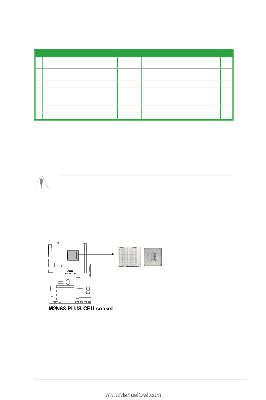
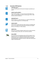
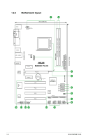
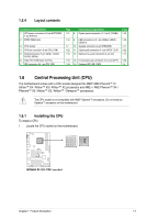
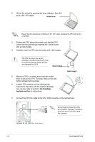
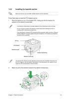
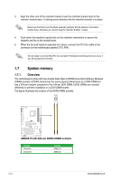
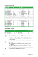
1.5.4 Layout contents Connectors/Jumpers/Slots 1. ATX power connectors (24-pin EATXPWR, 4-pin ATX12V) 2. DDR2 DIMM slots 3. CPU Socket 4. CPU fan connector (4-pin CPU_FAN) 5. SATA connectors (7-pin SATA1, SATA2, SATA3, SATA4) 6. Clear RTC RAM (3-pin CLRTC) 7. IDE connector (40-1 pin PRI_IDE) Page Connectors/Jumpers/Slots 1-21 8. System panel connector (10-1 pin F_PANEL) 1-10 9. USB connectors (10-1 pin USB56, USB78, USB910) 1-7 10. Speaker connector (4-pin SPEAKER) 1-22 11. Digital audio connector (4-1 pin SPDIF_OUT) 1-19 12. Optical drive audio connector (4-pin CD) 1-15 13. Front panel audio connector (10-1 pin AAFP) 1-18 14. Onboard LED (SB_PWR) Page 1-23 1-20 1-17 1-22 1-17 1-20 1-4 1.6 Central Processing Unit (CPU) The motherboard comes with a CPU socket designed for AMD® AM3 Phenom™ II / Athlon™ X4 / Athlon™ X3 / Athlon™ X2 processors and AM2+ / AM2 Phenom™ X4 / Phenom™ X3 / Athlon™ X2 / Athlon™ / Sempron™ processors. The CPU socket is not compatible with AMD® Opteron™ processors. Do not install an Opteron™ processor on this motherboard. 1.6.1 Installing the CPU To install a CPU: 1. Locate the CPU socket on the motherboard. Chapter 1: Product introduction 1-7
-
 1
1 -
2
-
3
-
4
-
5
-
6
-
7
-
8
-
9
-
10
-
11
-
 12
12 -
 13
13 -
 14
14 -
 15
15 -
 16
16 -
 17
17 -
 18
18 -
 19
19 -
 20
20 -
 21
21 -
 22
22 -
23
-
24
-
25
-
26
-
27
-
28
-
29
-
30
-
31
-
32
-
33
-
34
-
35
-
36
-
37
-
38
-
39
-
40
-
41
-
42
-
43
-
44
-
45
-
46
-
47
-
48
-
49
-
50
-
51
-
52
-
53
-
54
 |
 |