Asus M4N68T-MV2 User Manual - Page 16
Motherboard overview - m v2 motherboard
 |
View all Asus M4N68T-MV2 manuals
Add to My Manuals
Save this manual to your list of manuals |
Page 16 highlights
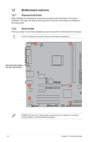
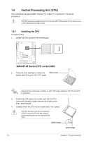
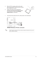
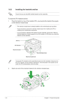
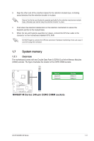
1.5 Motherboard overview 1.5.1 Placement direction When installing the motherboard, ensure that you place it into the chassis in the correct orientation. The edge with external ports goes to the rear part of the chassis as indicated in the image below. 1.5.2 Screw holes Place six screws into the holes indicated by circles to secure the motherboard to the chassis. DO NOT overtighten the screws! Doing so can damage the motherboard. Place this side towards the rear of the chassis. M4N68T-M V2 M4N68T-M V2 uses 100% all high-quality conductive polymer capacitors for durability, improved lifespan, and enhanced thermal capacity. 1-6 Chapter 1: Product introduction
-
 1
1 -
2
-
3
-
4
-
5
-
6
-
7
-
8
-
9
-
10
-
 11
11 -
 12
12 -
 13
13 -
 14
14 -
 15
15 -
 16
16 -
 17
17 -
 18
18 -
 19
19 -
 20
20 -
 21
21 -
22
-
23
-
24
-
25
-
26
-
27
-
28
-
29
-
30
-
31
-
32
-
33
-
34
-
35
-
36
-
37
-
38
-
39
-
40
-
41
-
42
-
43
-
44
-
45
-
46
-
47
-
48
-
49
-
50
-
51
-
52
-
53
-
54
-
55
-
56
-
57
-
58
-
59
-
60
-
61
-
62
-
63
-
64
-
65
-
66
 |
 |
M4N68T-M V2
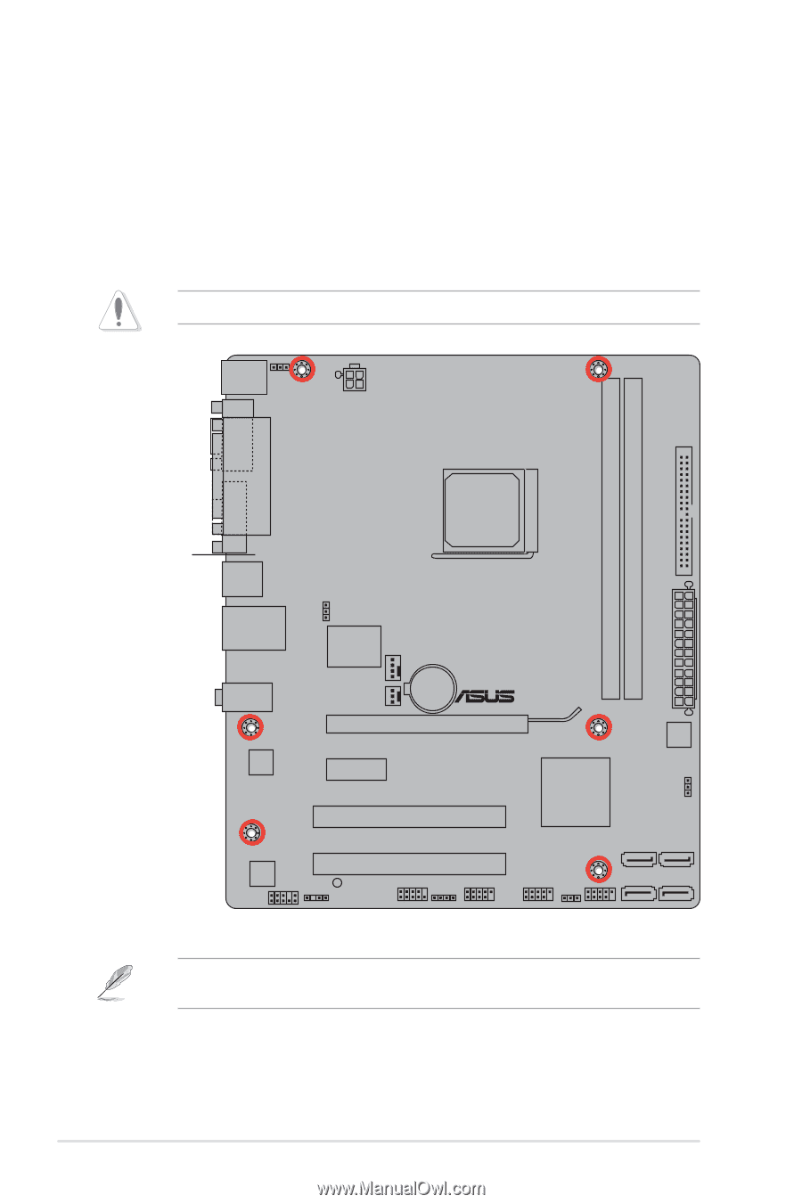
1.5
Motherboard overview
1.5.1
Placement direction
When installing the motherboard, ensure that you place it into the chassis in the correct
orientation. The edge with external ports goes to the rear part of the chassis as indicated in
the image below.
DO NOT overtighten the screws! Doing so can damage the motherboard.
1.5.2
Screw holes
Place six screws into the holes indicated by circles to secure the motherboard to the chassis.
Place this side towards
the rear of the chassis.
M4N68T-M V2 uses 100% all high-quality conductive polymer capacitors for durability,
improved lifespan, and enhanced thermal capacity.
Chapter 1: Product introduction
1-6