Asus M4N78-AM V2 User Manual - Page 18
Internal connectors
 |
View all Asus M4N78-AM V2 manuals
Add to My Manuals
Save this manual to your list of manuals |
Page 18 highlights
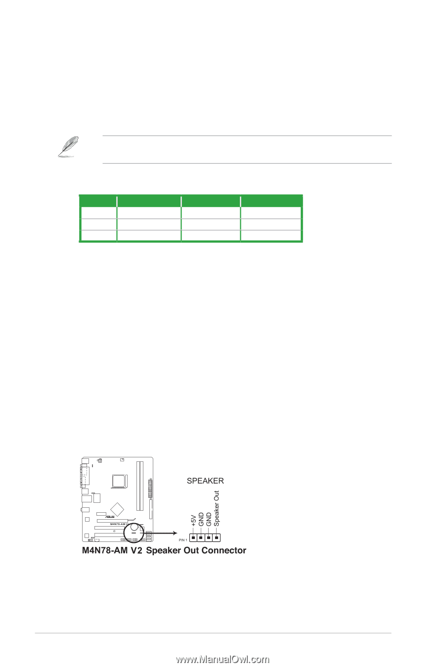
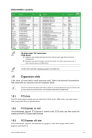
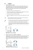
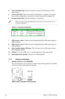
4. Line In port (light blue). This port connects to the tape, CD, DVD player, or other audio sources. 5. Line Out port (lime). This port connects to a headphone or a speaker. In 4-channel and 6-channel configurations, the function of this port becomes Front Speaker Out. 6. Microphone port (pink). This port connects to a microphone. Refer to the audio configuration table below for the function of the audio ports in 2, 4, or 6-channel configuration. Audio 2, 4, 6-channel configuration Port Light Blue Lime Pink Headset 2-channel Line In Line Out Mic In 4-channel Rear Speaker Out Front Speaker Out Mic In 6-channel Rear Speaker Out Front Speaker Out Bass/Center 7. USB 2.0 ports 1 and 2. These two 4-pin Universal Serial Bus (USB) ports connect to USB 2.0 devices. 8. USB 2.0 ports 3 and 4. These two 4-pin Universal Serial Bus (USB) ports connect to USB 2.0 devices. 9. Video Graphics Adapter (VGA) port. This 15-pin port is for a VGA monitor or other VGA-compatible devices. 10. COM port. This 9-pin COM1 port is for pointing devices or other serial devices. 11. PS/2 Keyboard port (purple). This port is for a PS/2 keyboard. 1.7.2 Internal connectors 1. Speaker connector (4- pin SPEAKER) This 4-pin connector is for the chassis-mounted system warning speaker. The speaker allows you to hear system beeps and warnings. 1-9 Chapter 1: Product introduction
-
 1
1 -
2
-
3
-
4
-
5
-
6
-
7
-
8
-
9
-
10
-
11
-
12
-
 13
13 -
 14
14 -
 15
15 -
 16
16 -
 17
17 -
 18
18 -
 19
19 -
 20
20 -
 21
21 -
 22
22 -
 23
23 -
24
-
25
-
26
-
27
-
28
-
29
-
30
-
31
-
32
-
33
-
34
-
35
-
36
-
37
-
38
-
39
-
40
 |
 |