Asus MAXIMUSII/FORMULA User Manual - Page 84
CPU Voltage [Auto], CPU PLL Voltage [Auto], FSB Termination Voltage [Auto], DRAM Voltage [Auto],
 |
UPC - 610839163052
View all Asus MAXIMUSII/FORMULA manuals
Add to My Manuals
Save this manual to your list of manuals |
Page 84 highlights
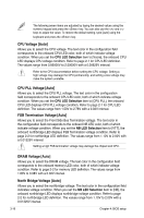
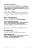
The following seven items are adjusted by typing the desired values using the numeric keypad and press the key. You can also use the and keys to adjust the value. To restore the default setting, type [auto] using the keyboard and press the key. CPU Voltage [Auto] Allows you to select the CPU voltage. The text color in the configuration field corresponds to the onboard CPU LED color, both of which indicate voltage condition. When you set the CPU LED Selection item to [Vcore], the onboard CPU LED displays CPU voltage condition. Refer to page 2-1 for CPU LED definition. The values range from 0.85000V to 2.50000V with a 0.00625V interval. Refer to the CPU documentation before setting the CPU voltage. Setting a high voltage may damage the CPU permanently, and setting a low voltage may make the system unstable. CPU PLL Voltage [Auto] Allows you to select the CPU PLL voltage. The text color in the configuration field corresponds to the onboard CPU LED color, both of which indicate voltage condition. When you set the CPU LED Selection item to [CPU PLL], the onboard CPU LED displays CPU PLL voltage condition. Refer to page 2-1 for CPU LED definition. The values range from 1.50V to 2.78V with a 0.02V interval. FSB Termination Voltage [Auto] Allows you to select the Front Side Bus Termination voltage. The text color in the configuration field corresponds to the onboard NB LED color, both of which indicate voltage condition. When you set the NB LED Selection item to [VTT], the onboard northbridge LED displays FSB Termination voltage condition. Refer to page 2-2 for northbridge LED definition. The values range from 1.10V to 2.00V with a 0.01325V interval. Setting a high FSB termination voltage may damage the chipset and CPU. DRAM Voltage [Auto] Allows you to select the DRAM voltage. The text color in the configuration field corresponds to the onboard memory LED color, both of which indicate voltage condition. Refer to page 2-2 for memory LED definition. The values range from 1.80V to 3.08V with a 0.02V interval. North Bridge Voltage [Auto] Allows you to select the northbridge voltage. The text color in the configuration field indicates voltage condition. When you set the NB LED Selection item to [NB], the onboard northbridge LED displays northbridge voltage condition. Refer to page 2-2 for northbridge LED definition. The values range from 1.10V to 2.00V with a 0.01325V interval. 3-16 Chapter 4: BIOS setup
-
 1
1 -
2
-
3
-
4
-
5
-
6
-
7
-
8
-
9
-
10
-
11
-
12
-
13
-
14
-
15
-
16
-
17
-
18
-
19
-
20
-
21
-
22
-
23
-
24
-
25
-
26
-
27
-
28
-
29
-
30
-
31
-
32
-
33
-
34
-
35
-
36
-
37
-
38
-
39
-
40
-
41
-
42
-
43
-
44
-
45
-
46
-
47
-
48
-
49
-
50
-
51
-
52
-
53
-
54
-
55
-
56
-
57
-
58
-
59
-
60
-
61
-
62
-
63
-
64
-
65
-
66
-
67
-
68
-
69
-
70
-
71
-
72
-
73
-
74
-
75
-
76
-
77
-
78
-
 79
79 -
 80
80 -
 81
81 -
 82
82 -
 83
83 -
 84
84 -
 85
85 -
 86
86 -
 87
87 -
 88
88 -
 89
89 -
90
-
91
-
92
-
93
-
94
-
95
-
96
-
97
-
98
-
99
-
100
-
101
-
102
-
103
-
104
-
105
-
106
-
107
-
108
-
109
-
110
-
111
-
112
-
113
-
114
-
115
-
116
-
117
-
118
-
119
-
120
-
121
-
122
-
123
-
124
-
125
-
126
-
127
-
128
-
129
-
130
-
131
-
132
-
133
-
134
-
135
-
136
-
137
-
138
-
139
-
140
-
141
-
142
-
143
-
144
-
145
-
146
-
147
-
148
-
149
-
150
-
151
-
152
-
153
-
154
-
155
-
156
-
157
-
158
-
159
-
160
-
161
-
162
-
163
-
164
-
165
-
166
-
167
-
168
-
169
-
170
-
171
-
172
-
173
-
174
 |
 |