Asus MW201U User Guide - Page 11

Rear of the LCD monitor - mw201

Page 11 highlights

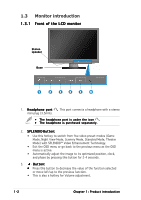
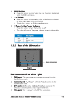
4. M E N U B u t t o n : • Press this button to enter/select the icon (function) highlighted while the OSD is activated. 5. Button: • Press this button to increase the value of the function selected or move right/down to the next fuction. • This is also a hotkey for Brightness adjustment. 6. Power button/power indicator • Press this button to turn the monitor on/off • The color definition of the power indicator is as the below table. Status Blue Amber OFF Description ON Standby mode OFF 1.3.2 Rear of the LCD monitor Rear connectors Rear connectors (from left to right) 1. P W R p o r t . This port connects the power connector from the bundled power cord. 2. A u d i o - i n p o r t . This port connects PC audio source by the bundled audio cable. 3. D V I p o r t(only for some models). This 24-pin port is for PC (Personal Computer) DVI-D digital signal connection. 4. V G A p o r t . This 15-pin port is for PC VGA connection. ASUS LCD Monitor MW221/MW201 Series 1-3

  • 1
  • 2
  • 3
  • 4
  • 5
  • 6
  • 7
  • 8
  • 9
  • 10
  • 11
  • 12
  • 13
  • 14
  • 15
  • 16
  • 17
  • 18
  • 19
  • 20
  • 21
  • 22

1-3
1-3
1-3
1-3
1-3
ASUS LCD Monitor MW221/MW201 Series
1.3.2
1.3.2
1.3.2
1.3.2
1.3.2
Rear of the LCD monitor
Rear connectors
Rear connectors
Rear connectors
Rear connectors
Rear connectors
4.
MENU Button:
MENU Button:
MENU Button:
MENU Button:
MENU Button:
Press this button to enter/select the icon (function) highlighted
while the OSD is activated.
5.
Button:
Button:
Button:
Button:
Button:
Press this button to increase the value of the function selected
or move right/down to the next fuction.
This is also a hotkey for Brightness adjustment.
6.
Power button/power indicator
Press this button to turn the monitor on/off
The color definition of the power indicator is as the below table.
1.
PWR port.
PWR port.
PWR port.
PWR port.
PWR port. This port connects the power connector from the
bundled power cord.
2.
Audio-in port
Audio-in port
Audio-in port
Audio-in port
Audio-in port
.
.
.
.
. This port connects PC audio source by the
bundled audio cable.
3.
DVI port
DVI port
DVI port
DVI port
DVI port
This 24-pin port is for PC
digital signal connection.
4.
VGA port.
VGA port.
VGA port.
VGA port.
VGA port. This 15-pin port is for PC VGA connection.
Rear connectors (from left to right)
Status
Description
Status
Description
Status
Description
Status
Description
Status
Description
Blue
ON
Amber
Standby mode
OFF
OFF
.
(
only for some models
)
(Personal Computer) DVI-D