Asus N3050I-CM-A Users Manual English - Page 11
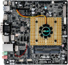
Flat panel display brightness connector 8-pin, LCD_BLKT_PANEL, Dual-core N3050 Processor
 |
View all Asus N3050I-CM-A manuals
Add to My Manuals
Save this manual to your list of manuals |
Page 11 highlights
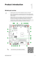
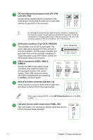
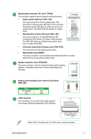
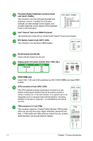
Flat panel display brightness connector (8-pin LCD_BLKT_PANEL) This connector is for the LCD panel backlight and brightness controls. It enables the LCD panel backlight, provides backlight control signals, and provides brightness control signals for the brightness button on the front panel. LCD_BLKT_PANEL PIN 1 Brightness_Down Brightness_up BKLT_GND/Brightness_GND BKLT_GND/Brightness_GND BKLT_PWR BKLT_PWR BKLT_PWM BKLT_EN Intel® Celeron® Dual-core N3050 Processor The motherboard comes with an onboard Intel® Celeron® Dual-core processor. RTC Battery header (2-pin BATT_CON) This connector is for the lithium CMOS battery. BATT_CON VBAT GND PIN 1 WLAN module slot (WLAN) Install a WLAN module into this slot. Display panel VCC power selector (VCC_PWR_SEL) Pins 1 (Default) 2 3 Setting 3V 5V 12V VCC_PWR_SEL 1 3V (Default) 2 5V 3 12V DDR3 DIMM slots Install 2 GB, 4 GB, and 8 GB unbuffered non-ECC DDR3 DIMMs into these DIMM sockets. GPIO connector (10-pin GPIO_CON) This GPIO (general purpose input/output) connector is a very flexible multi-purpose interface that can be used to connect a variety of simple one- or two-wire devices. It is a generic pin on an integrated circuit or computer board whose behavior-including whether it is an input or output pin-is controllable by the user at run time. GND GP40 GP41 GP42 +5V GP43 GP44 GP45 GP46 GP47 GPIO_CON PIN 1 TPM connector (14-1 pin TPM) This connector supports a Trusted Platform Module (TPM) system, which can securely store keys, digital certificates, passwords and data. A TPM system also helps enhance network security, protects digital identities, and ensures platform integrity. TPM_PD# F_SERIRQ F_FRAME# F_LAD3 F_LAD2 F_LAD1 F_LAD0 TPM PIN 1 +3VSB S_PCIRST#_TBD GND C_PCICLK_TPM +3V +3V 1-4 Chapter 1: Product introduction
-
 1
1 -
2
-
3
-
4
-
5
-
 6
6 -
 7
7 -
 8
8 -
 9
9 -
 10
10 -
 11
11 -
 12
12 -
 13
13 -
 14
14 -
 15
15 -
 16
16 -
17
-
18
-
19
-
20
-
21
-
22
-
23
-
24
-
25
-
26
-
27
 |
 |
