Asus N3050I-CM-A Users Manual English - Page 13
CLRTC, COM4 Ring/+5V/+12V selection 6-pin J5
 |
View all Asus N3050I-CM-A manuals
Add to My Manuals
Save this manual to your list of manuals |
Page 13 highlights
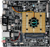
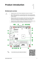
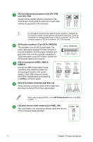
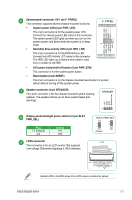
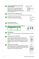
Clear RTC RAM (2-pin CLRTC) This header allows you to clear the CMOS RTC RAM data of the system setup information such as date, time, and system passwords. To erase the RTC RAM: 1. Turn OFF the computer and unplug the power cord. 2. Use a metal object such as a screwdriver to short the two pins. 3. Plug the power cord and turn ON the computer. 4. Hold down the key during the boot process and enter BIOS setup to re-enter data. +3V_BAT GND CLRTC PIN 1 If the steps above do not help, remove the onboard battery and short the two pins again to clear the CMOS RTC RAM data. After clearing the CMOS, reinstall the battery. Serial port connectors (10-1 pin COM2/3/4) Connect the serial port module cable to one of theses connectors, then install the module to a slot opening at the back of the system chassis. COM4 PIN 1 DCD TXD GND RTS RI RXD DTR DSR CTS COM3 PIN 1 DCD TXD GND RTS RI RXD DTR DSR CTS COM2 PIN 1 DCD TXD GND RTS RI RXD DTR DSR CTS COM4 Ring/+5V/+12V selection (6-pin J5) Pins Pins +12V 1-2 +5V 3-4 Ring (Default) 5-6 J5 21 43 65 +12V +5V Ring (Default) mSATA/mPCIe combo slot (MSATA_MPCIE) This slot allows you to install a full length mSATA or mini-PCIe card, providing you with expandability and connectivity solutions for an optimal system performance. • mSATA shares the same slot with the full-length mini-PCIe card. • mSATA shares the same bandwidth with SATA6G_2 slot. When a device is installed on the SATA6G_2 slot, the mSATA device is disabled. 1-6 Chapter 1: Product introduction
-
 1
1 -
2
-
3
-
4
-
5
-
6
-
7
-
 8
8 -
 9
9 -
 10
10 -
 11
11 -
 12
12 -
 13
13 -
 14
14 -
 15
15 -
 16
16 -
 17
17 -
 18
18 -
19
-
20
-
21
-
22
-
23
-
24
-
25
-
26
-
27
 |
 |
