Asus N3050I-CM-A Users Manual English - Page 9
Serial ATA 6.0Gb/s connectors SATA6G_1/2, USB 2.0 connectors USBE5, USBE12
 |
View all Asus N3050I-CM-A manuals
Add to My Manuals
Save this manual to your list of manuals |
Page 9 highlights
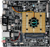
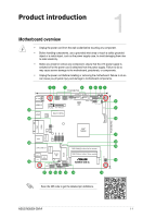
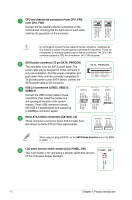
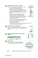
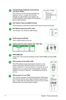
CPU and chassis fan connectors (4-pin CPU_FAN, 4-pin CHA_FAN) Connect the fan cables to the fan connectors on the motherboard, ensuring that the black wire of each cable matches the ground pin of the connector. CHA_FAN CPU_FAN CHA FAN PWM CHA FAN IN CHA FAN PWR GND CPU FAN PWM CPU FAN IN CPU FAN PWR GND Do not forget to connect the fan cables to the fan connectors. Insufficient air flow inside the system may damage the motherboard components. These are not jumpers! Do not place jumper caps on the fan connectors! The CPU_FAN connector supports a CPU fan of maximum 1A (12 W) fan power. SATA power connector (15-pin SATA_PWRCON) This connector is for the SATA power cable. The power cable plug is designed to fit this connector in only one orientation. Find the proper orientation and push down firmly until the connector completely fit. To provide power to your SATA device, connect the SATA power cable to this connector +12V +12V +12V GND GND GND +5V +5V +5V GND GND GND +3V +3V +3V SATA_PWRCON PIN 1 USB 2.0 connectors (USBE5, USBE12, USBE34) USBE12 USBE34 USBE5 +5V DC Data(negative) Data(positive) Groud USB+5V USB_P4USB_P4+ GND NC USB+5V USB_P1USB_P1+ GND NC Connect the USB module cable to these connectors, then install the module to a slot opening at the back of the system PIN 1 PIN 1 chassis. These USB connectors comply PIN 1 USB+5V USB_P4USB_P4+ GND USB+5V USB_P2USB_P2+ GND with USB 2.0 specifications and support up to 480Mbps connection speed. Serial ATA 6.0Gb/s connectors (SATA6G_1/2) These connectors connect to Serial ATA 6.0 Gb/s hard disk drives via Serial ATA 6.0 Gb/s signal cables. GND RSATA_RXP2 RSATA_RXN2 GND RSATA_TXN2 RSATA_TXP2 GND GND RSATA_RXP1 RSATA_RXN1 GND RSATA_TXN1 RSATA_TXP1 GND SATA6G_2 SATA6G_1 When using hot-plug and NCQ, set the SATA Mode Selection item in the BIOS to [AHCI LCD panel monitor switch header (2-pin PANEL_SW) This 2-pin header is for connecting a monitor switch that can turn off the LCD panel display backlight. PANEL_SW PIN 1 MON_SW# GND 1-2 Chapter 1: Product introduction
-
 1
1 -
2
-
3
-
 4
4 -
 5
5 -
 6
6 -
 7
7 -
 8
8 -
 9
9 -
 10
10 -
 11
11 -
 12
12 -
 13
13 -
 14
14 -
15
-
16
-
17
-
18
-
19
-
20
-
21
-
22
-
23
-
24
-
25
-
26
-
27
 |
 |
