Asus NCLV-DS2 User Manual
Asus NCLV-DS2 Manual
 |
View all Asus NCLV-DS2 manuals
Add to My Manuals
Save this manual to your list of manuals |
Asus NCLV-DS2 manual content summary:
- Asus NCLV-DS2 | User Manual - Page 1
Motherboard NCLV-D2 Series NCLV-D2/SATA NCLV-DS2 - Asus NCLV-DS2 | User Manual - Page 2
express written permission of ASUSTeK COMPUTER INC. ("ASUS"). Product warranty or service will not be extended if: (1) the product manual may or may not be registered trademarks or copyrights of their respective companies, and are used only for identification or explanation and to the owners' benefit - Asus NCLV-DS2 | User Manual - Page 3
Product highlights 1-2 1.3.2 Innovative ASUS features 1-4 Chapter 2: Hardware information 2.1 Before you proceed 2-1 2.2.1 Placement direction 2-2 2.2.2 Screw holes 2-2 2.2 Motherboard overview 2-2 2.2.3 Support kit for motherboard 2-3 2.2.4 Motherboard layouts 2-6 2.2.5 Layout contents - Asus NCLV-DS2 | User Manual - Page 4
BIOS setup 4.1 Managing and updating your BIOS 4-1 4.1.1 Creating a bootable floppy disk 4-1 4.1.2 AFUDOS utility 4-2 4.1.3 ASUS CrashFree BIOS 2 utility 4-5 4.1.4 ASUS Update utility 4-7 4.2 BIOS setup program 4-10 4.2.1 BIOS Hardware Monitor 4-28 4.5 Server menu 4-30 4.5.1 Remote Access - Asus NCLV-DS2 | User Manual - Page 5
5-26 5.4 Adaptec SCSISelect(TM) Utility (NCLV-DS2 model only) ... 5-27 5.4.1 Configuring the SCSI controller 5-28 5.4.2 Enabling the HostRAID controller 5-28 5.4.3 Creating a RAID 0 set (Stripe 5-29 5.4.4 Creating a RAID 1 set (Mirror 5-33 5.4.5 Creating a RAID 10 set (Stripe+Mirror 5-36 - Asus NCLV-DS2 | User Manual - Page 6
applications and utilities installation 6-16 6.4.1 Running the support CD 6-16 6.4.2 Drivers menu 6-16 6.4.3 Management Software menu 6-17 6.4.4 Utilities menu 6-17 6.4.5 Contact information 6-17 Appendix: Block diagrams A.1 NCLV-D2/SATA block diagram A-1 A.2 NCLV-DS2 block diagram A-2 vi - Asus NCLV-DS2 | User Manual - Page 7
and, if not installed and used in accordance with manufacturer's instructions, may cause harmful interference to radio communications. However, there is reception, which can be determined by turning the equipment off and on, the user is encouraged to try to correct the interference by one or more of - Asus NCLV-DS2 | User Manual - Page 8
Contact a qualified service technician or your retailer. Operation safety • Before installing the motherboard and adding devices on it, carefully read all the manuals that came with • If you encounter technical problems with the product, contact a qualified service technician or your retailer. viii - Asus NCLV-DS2 | User Manual - Page 9
guide This user guide contains the information you need when installing and configuring the motherboard. How this guide is organized This guide contains the following parts: • Chapter 1: Product introduction This chapter describes the features of the motherboard and the new technologies it supports - Asus NCLV-DS2 | User Manual - Page 10
following symbols used throughout this manual. D A N G E R / W A R N I N G : Information to prevent injury to yourself when trying to complete a task. C A U T I O N : Information to prevent damage to the components when trying to complete a task. I M P O R T A N T : Instructions that you MUST follow - Asus NCLV-DS2 | User Manual - Page 11
5V slot (PCI 2.3) 1 x mini-PCI socket for ASUS® Server Management Board Both models: Intel® 6300ESB Southbridge supports: - 4 x Ultra DMA 100/66/33 devices - 2 x SATA-150 HDDs with RAID 0 and RAID 1 configuration via the embedded LSI Logic Embedded SATA RAID controller Adaptec® AIC-8130 PCI-X SATAII - Asus NCLV-DS2 | User Manual - Page 12
(both models) 4 x Serial ATA RAID connectors (NCLV-D2/SATA model only) Ultra320 SCSI connector (NCLV-DS2 model only) USB 2.0/1.1 connector Serial port 10.5 in (30.5 cm x 26.7 cm) Device drivers ASUS Live Update Utility ASUS Server Web-based Management (ASWM) Anti-virus software *Specifications are - Asus NCLV-DS2 | User Manual - Page 13
This chapter describes the motherboard features and the new technologies it supports. 1Product introduction - Asus NCLV-DS2 | User Manual - Page 14
Chapter summary 1 1.1 Welcome 1-1 1.2 Package contents 1-1 1.3 Special features 1-2 ASUS NCLV-D2 Series - Asus NCLV-DS2 | User Manual - Page 15
pc for NCLV-DS2 model • 3 pcs for NCLV-D2/SATA model SCSI Ultra320 cable ( N C L V - D S 2 m o d e l o n l y ) 80-conductor IDE cable 3-in-1 floppy disk drive cable Accessories 2 x CEK springs (for CPUs) CPU heatsink support kit* I/O shield A p p l i c a t i o n C D s ASUS motherboard support CD - Asus NCLV-DS2 | User Manual - Page 16
2-19 for details. Ultra320 SCSI feature (NCLV-DS2 model only) The Adaptec® AIC-7901X PCI-X SCSI controller is onboard to support one 68-pin Ultra320 SCSI connector, that can connect up to 15 SCSI devices. See page 2-30 for details. Serial ATA II feature (NCLV-D2/SATA model only) The Adaptec® AIC - Asus NCLV-DS2 | User Manual - Page 17
The motherboard supports the Serial ATA technology through the Serial ATA interfaces controlled by the Intel® 6300ESB. The SATA specification allows for thinner, more flexible cables with lower pin count, reduced voltage requirement, and up to 150 MB/s data transfer rate. Built-in SATA RAID solution - Asus NCLV-DS2 | User Manual - Page 18
BIOS data from the support CD in case when the BIOS codes and data are corrupted. This protection eliminates the need to buy a replacement ROM chip. See page 4-5 for details. ASUS Smart Fan Control technology The ASUS for details. ASUS MyLogo2™ This new feature present in the motherboard allows you - Asus NCLV-DS2 | User Manual - Page 19
This chapter lists the hardware setup procedures that you have to perform when installing system components. It includes description of the jumpers and connectors on the motherboard. 2 Hardware information - Asus NCLV-DS2 | User Manual - Page 20
Chapter summary 2 2.1 Before you proceed 2-1 2.2 Motherboard overview 2-2 2.3 Central Processing Unit (CPU 2-10 2.4 System memory 2-14 2.5 Expansion slots 2-17 2.6 Jumpers 2-20 2.7 Connectors 2-26 ASUS NCLV-D2 Series - Asus NCLV-DS2 | User Manual - Page 21
This is a reminder that you should shut down the system and unplug the power cable before removing or plugging in any motherboard component. The illustration below shows the location of the onboard LED. SB_PWR1 ON Standby Power NCLV-D2 Series Onboard LED OFF Powered Off ASUS NCLV-D2 Series 2-1 - Asus NCLV-DS2 | User Manual - Page 22
sure to unplug the chassis power cord before installing or removing the motherboard. Failure to do so can cause you physical injury and damage motherboard components! 2.2.1 Placement direction When installing the motherboard, make sure that you place it into the chassis in the correct orientation - Asus NCLV-DS2 | User Manual - Page 23
holes around the CPU area. Hook To install the CEK spring: 1. Locate the CPU heatsink holes on the motherboard. Socket for CPU2 Socket for CPU1 Heatsink hole 2. Position the CEK spring underneath the motherboard, then match the CEK spring hooks to the CPU1 heatsink holes. ASUS NCLV-D2 Series 2-3 - Asus NCLV-DS2 | User Manual - Page 24
3. Insert the hooks on one side of the spring to the heatsink holes. 4. Push the hooks on the other side of the spring inward until they snap in place. 5. If you installed a second CPU, repeat steps 2 to 4 to install the CEK spring to the CPU2 heatsink holes. The CEK springs appear as shown when - Asus NCLV-DS2 | User Manual - Page 25
CEK spring screw holes. Standoffs for CPU1 Standoffs for CPU2 7. Install the motherboard with the external I/O ports toward the chassis rear panel. The CPU sockets properly. 8. Secure the motherboard with 9 screws. Refer to section "2.2.2 Screw holes" for illustration. ASUS NCLV-D2 Series 2-5 - Asus NCLV-DS2 | User Manual - Page 26
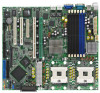
(12in) 2.2.4 Motherboard layouts NCLV-D2/SATA model mPGA 604 26.8cm (10.5in) PS/2KBMS T: B: Mouse Keyboard KBPWR1 SSIPWR1 SSI12V1 NCLV-D2/SATA USB12 REAR_FAN1 PSUSMB1 VGA_EN1 PCI4 (32-bit 5V PCI) Super I/O 8Mbit Flash BIOS CLRTC1 SB_PWR1 RECOVERY1 PCI5 (32-bit 5V PCI) CR2032 3V - Asus NCLV-DS2 | User Manual - Page 27
(10.5in) PS/2KBMS T: B: Mouse Keyboard KBPWR1 SSIPWR1 SSI12V1 NCLV-DS2 USB12 REAR_FAN1 PSUSMB1 COM1 USBPW12 DDR2 DDR_B3 (64 bit,240-pin PCIE1(x4 link) VGA_EN1 PCI4 (32-bit 5V PCI) Super I/O 8Mbit Flash BIOS CLRTC1 SB_PWR1 RECOVERY1 PCI5 (32-bit 5V PCI) CR2032 3V Lithium Cell CMOS - Asus NCLV-DS2 | User Manual - Page 28
CPU sockets 2. DDR2 DIMM sockets 3. PCI/PCI-X/PCI Express slots 4. Zero-Channel RAID socket Jumpers 1. Clear RTC RAM (CLRTC1) 2. CPU fan pin selection (3-pin SCSI controller setting (3-pin SCSI_EN1) 9. SATA controller setting (3-pin SATA_EN1) 10. Adaptec 8130 LED setting (3-pin LED1) 11. Force BIOS - Asus NCLV-DS2 | User Manual - Page 29
ATA connectors (7-pin SATA1, SATA2) 4. Serial ATA RAID connectors (two 68-pin SCSIA1, SCSIB1) 5. Hard disk activity LED connector (4-pin HDLED1) 6. Ultra320 SCSI connectors 7. USB connector (10-1 pin USB34) 8. 2-29 2-29 2-30 2-31 2-31 2-32 2-32 2-33 2-33 2-34 2-35 2-36 ASUS NCLV-D2 Series 2-9 - Asus NCLV-DS2 | User Manual - Page 30
L2 cache. The new generation Xeon™ processor supports 800 MHz system bus and Extended Memory 64-bit Technology (EM64T). 2.3.1 Installling the CPU To install a CPU: 1. Locate the CPU sockets on the motherboard. CPU1 Intel Xeon CPU2 Gold Arrow Pin A1 NCLV-D2 Series CPU Socket 604 If installing - Asus NCLV-DS2 | User Manual - Page 31
the CPU. This thermal grease should come with the CPU package. 7. Repeat steps 1 to 6 if you wish to install a second CPU. Marked corner (gold arrow) ASUS NCLV-D2 Series 2-11 - Asus NCLV-DS2 | User Manual - Page 32
to the top of the CPU before installing the heatsink and fan. • Refer to the installation manual that came with the CPU package for details on heatsink/fan assembly and installation. CPU heatsink (top on the heatsink align with the nuts on the support plate. 2-12 Chapter 2: Hardware information - Asus NCLV-DS2 | User Manual - Page 33
you have installed a second CPU, then connect the fan cable to the 4-pin connector labeled CPU_FAN2. The heatsinks appear as shown when installed. CPU_FAN2 connector ASUS NCLV-D2 Series CPU_FAN1 connector 2-13 - Asus NCLV-DS2 | User Manual - Page 34
motherboard comes with six Double Data Rate II (DDR2) Dual Inline Memory Modules (DIMM) sockets to support 240-pin DDR modules. The figure illustrates the location of the DDR DIMM sockets: 128 Pins NCLV to the DDR2 Qualified Vendors List at the ASUS web site. • Due to chipset resource allocation - Asus NCLV-DS2 | User Manual - Page 35
MCH Dual Rank DIMM B3 Dual Rank DIMM A3 Single Rank DIMM B2 Single Rank DIMM A2 Single Rank DIMM B1 Single Rank DIMM A1 ASUS NCLV-D2 Series 2-15 - Asus NCLV-DS2 | User Manual - Page 36
components. Failure to do so may cause severe damage to both the motherboard and the components. To install a DIMM: 1. Unlock a DIMM socket into a socket to avoid damaging the DIMM. • The DDR2 DIMM sockets do not support DDR DIMMs. DO NOT install DDR DIMMs to the DDR2 DIMM sockets. 2.4.4 Removing - Asus NCLV-DS2 | User Manual - Page 37
your motherboard drivers for the expansion card. When using PCI cards on shared slots, ensure that the drivers support "Share IRQ" or that the cards do not need IRQ assignments. Otherwise, conflicts will arise between the two PCI groups, making the system unstable and the card inoperable. ASUS NCLV - Asus NCLV-DS2 | User Manual - Page 38
for ISA or PCI devices. PCI Bus Number, IDSEL, and IRQ assignments Description IDE Controller SATA Controller SMBus Controller USB UHCI Controller #1 USB UHCI Controller #2 USB 2.0 EHCI Controller AIC7901 SCSI controller ATI RAGE XL PCIX Slot 1 PCIX Slot 2 PCI Express Slot3 PCIX Slot 4 PCIX Slot - Asus NCLV-DS2 | User Manual - Page 39
MCH. This slot is designed for various server class high performance add-on cards like SCSI RAID card, fiber-channel card, etc. 2.5.6 ZCR slot The 64-bit PCI-X slot (green) on the motherboard supports a Zero-Channel RAID card that allows all types of RAID configurations. ASUS NCLV-D2 Series 2-19 - Asus NCLV-DS2 | User Manual - Page 40
pins 1-2. 4. Re-install the battery. 5. Plug the power cord and turn ON the computer. 6. Hold down the key during the boot process and enter BIOS setup to re-enter data. Except when clearing the RTC RAM, never remove the cap on CLRTC jumper default position. Removing the cap will cause - Asus NCLV-DS2 | User Manual - Page 41
(Default) PWM FM_CPU2 21 32 DC mode (Default) NCLV-D2 Series FM_CPU Setting PWM 3 . USB device wake- (Default) +5VSB USBPW34 12 23 +5V (Default) NCLV-D2 Series USB device wake-up +5VSB • The you are using Windows 2000, you need to install Service Pack 4 to wake up the system from S4 - Asus NCLV-DS2 | User Manual - Page 42
requires an ATX power supply that can supply at least 1A on the +5VSB lead, and a corresponding setting in the BIOS. KBPWR1 12 23 +5V (Default) +5VSB NCLV-D2 Series Keyboard power setting 5 . VGA controller setting (3-pin VGA_EN1) These jumpers allow you to enable or disable the onboard - Asus NCLV-DS2 | User Manual - Page 43
1-2 to activate the Gigabit LAN feature. LAN_EN1 21 32 Enable (Default) Disable NCLV-D2 Series LAN_EN1 setting 7 . Gigabit LAN controller setting (3-pin LAN2_EN1) These Gigabit LAN feature. LAN_EN2 2 1 Enable (Default) 3 2 Disable NCLV-D2 Series LAN_EN2 setting ASUS NCLV-D2 Series 2-23 - Asus NCLV-DS2 | User Manual - Page 44
) (NCLV-DS2 model only) This jumper allows you to enable or disable the onboard Adaptec® AIC-7901X SCSI U320 controller. Set to pins 1-2 to activate the SCSI feature, and support RAID configurations. NCLV-D2 Series SCSI setting SCSI_EN1 1 2 Enable (Default) 2 3 Disable 9 . SATA controller - Asus NCLV-DS2 | User Manual - Page 45
only) This jumper allows you to enable or disable the LED related to the Adaptec® AIC-8130 SATA-II controller. 8130 LED1 12 23 Disable (Default) Enable NCLV-D2 Series 8130 LED setting 11. Force BIOS recovery setting (3-pin RECOVERY1) This jumper allows you to quickly update or recover the - Asus NCLV-DS2 | User Manual - Page 46
2.7 Connectors 2.7.1 Rear panel connectors 1 2 3 4 5 6 7 1 . P S / 2 m o u s e p o r t ( g r e e n ) . This port is for a PS/2 mouse. 2 . P S / 2 k e y b o a r d p o r t ( p u r p l e ) . This port is for a PS/2 keyboard. 3 . U S B 2 . 0 p o r t s 1 a n d 2 . These two 4-pin Universal Serial - Asus NCLV-DS2 | User Manual - Page 47
100/66 signal cable has three connectors: a blue connector for the primary IDE connector on the motherboard, a black connector for an Ultra DMA 100/66 IDE slave device (optical drive/hard disk drive zigzag) on the IDE ribbon cable to PIN 1. NCLV-D2 Series IDE connectors ASUS NCLV-D2 Series 2-27 - Asus NCLV-DS2 | User Manual - Page 48
GND NCLV-DS2 SATA connectors SATA1 GND RSATA_TXP1 RSATA_TXN1 GND RSATA_RXP1 RSATA_RXN1 GND Important notes on Serial ATA • You must install Windows® 2000 Service Pack 4 or the Windows® XP Service Pack 1 before using Serial ATA hard disk drives. The Serial ATA RAID feature (RAID 0 or RAID 1) is - Asus NCLV-DS2 | User Manual - Page 49
Master Boot disk SATA2 Slave Data disk 4 . Serial ATA RAID connectors (7-pin SATA_RAID1, SATA_RAID2, SATA_RAID3, SATA_RAID4) (NCLV-D2/SATA model only) These connectors are for the Serial ATA signal cables. These connectors support up to four SATA hard disk drives that you can configure as an - Asus NCLV-DS2 | User Manual - Page 50
connector (68-pin SCSI1) (NCLV-D2/SATA model only) This motherboard comes with the Adaptec® AIC-7901X PCI-X SCSI controller that supports one 68-Pin Ultra320 SCSI connector. The SCSI channel can support a maximum of 15 SCSI devices as specified by Ultra320 standards. SCSI1 68-Pin Ultra320/ 1 35 - Asus NCLV-DS2 | User Manual - Page 51
complies with USB 2.0 specification that supports up to 480 Mbps connection speed. USB+5V USB_P6USB_P6+ GND NC USB+5V USB_P5USB_P5+ GND USB34 NCLV-D2 Series USB 2.0 connector the system chassis. COM2 PIN 1 NCLV-D2 Series Serial port2 (COM2) connector The serial port module is purchased separately - Asus NCLV-DS2 | User Manual - Page 52
CPU_FAN2 GND FANPWR2 FANOUT4 GND FANPWR2 FANOUT4 FRNT_FAN1 FRNT_FAN2 FRNT_FAN1 NCLV-D2 Series Fan connectors FRNT_FAN2 Rotation +12V GND Rotation +12V GND 10. BMC connector (16-pin BMCCONN1) This connector is for the ASUS server management card, if available. +5VSB +5VSB BMC SMBCLK 12CCLK1 - Asus NCLV-DS2 | User Manual - Page 53
Series SMBus connector 12. Power supply SMBus connector (5-pin PSUSMB1) This connector is for the power supply SMB cable, if your power supply supports the SMBus function. PSUSMB1 NCLV-D2 Series Power supply SMBus connector PSU_I2CCLK PSU_I2CDATA NC GND +3.3V Remote Sense ASUS NCLV-D2 Series 2-33 - Asus NCLV-DS2 | User Manual - Page 54
Volts Ground +5 Volts Ground +5 Volts Ground Power OK +5V Standby +12 Volts +12 Volts +3 Volts +12V CPU +12V CPU +12V CPU +12V CPU 1 NCLV-D2 Series Power connectors +3 Volts -12 Volts Ground PSON# Ground Ground Ground -5 Volts +5 Volts +5 Volts +5 Volts Ground For Power Supply with 20-pin Power - Asus NCLV-DS2 | User Manual - Page 55
-pin PANEL1) This connector supports several chassis-mounted functions. puts the system in sleep or soft-off mode depending on the BIOS settings. Pressing the power switch for more than four seconds while the GND NC RESETBTN# GND PANEL1 NCLV-D2 Series System panel connector The system panel connector - Asus NCLV-DS2 | User Manual - Page 56
LED (6-pin LOCATOR) These leads are for the locator switch and LED on the front panel. AUX_PANEL1 PIN1 NCLV-D2 Series Auxiliary panel connector NC I2C_4_CLK# GND I2C_4_DATA# +3V LAN1_LINKACTLED+ LAN1_LINKACTLEDLAN2_LINKACTLEDLAN2_LINKACTLED+ +5VSB CASEOPEN GND LOCATORLED1+ LOCATORLED1- LOCATORBTN - Asus NCLV-DS2 | User Manual - Page 57
This chapter describes the power up Powerin3g up sequence, and ways of shutting down the system. - Asus NCLV-DS2 | User Manual - Page 58
Chapter summary 3 3.1 Starting up for the first time 3-1 3.2 Powering off the computer 3-2 ASUS NCLV-D2 Series - Asus NCLV-DS2 | User Manual - Page 59
with a surge protector. 5. Turn on the devices in the following order: a. Monitor b. External SCSI devices (starting with the last device on the chain) c. System power 6. After applying power, the key to enter the BIOS Setup. Follow the instructions in Chapter 4. ASUS NCLV-D2 Series 3-1 - Asus NCLV-DS2 | User Manual - Page 60
is ON, pressing the power switch for less than four seconds puts the system to sleep mode or to soft-off mode, depending on the BIOS setting. Pressing the power switch for more than four seconds lets the system enter the soft-off mode regardless of the - Asus NCLV-DS2 | User Manual - Page 61
This chapter tells how to change the system settings through the BIOS Setup menus. Detailed descriptions of the BIOS parameters are also provided. 4 BIOS setup - Asus NCLV-DS2 | User Manual - Page 62
Chapter summary 4 4.1 Managing and updating your BIOS 4-1 4.2 BIOS setup program 4-10 4.3 Main menu 4-13 4.4 Advanced menu 4-18 4.5 Server menu 4-30 4.6 Security 4-32 4.7 Boot menu 4-35 ASUS NCLV-D2 Series - Asus NCLV-DS2 | User Manual - Page 63
BIOS using a bootable floppy disk or the motherboard support CD when the BIOS file fails or gets corrupted.) 3. A S U S U p d a t e (Updates the BIOS options field, then click S t a r t. 2. Copy the original or the latest motherboard BIOS file to the bootable floppy disk. ASUS NCLV-D2 Series 4-1 - Asus NCLV-DS2 | User Manual - Page 64
is not write-protected and has at least 1024 KB free space to save the file. • The succeeding BIOS screens are for reference only. The actual BIOS screen displays may not be same as shown. 1. Copy the AFUDOS utility (afudos.exe) from the motherboard support CD to the bootable floppy disk you created - Asus NCLV-DS2 | User Manual - Page 65
(www.asus.com) and download the latest BIOS file for the motherboard. Save the BIOS file to a bootable floppy disk. Write the BIOS filename on a piece of paper. You need to type the exact BIOS filename at the DOS prompt. 2. Copy the AFUDOS utility (afudos.exe) from the motherboard support CD to - Asus NCLV-DS2 | User Manual - Page 66
5. The utility returns to the DOS prompt after the BIOS update process is completed. Reboot the system from the hard disk drive. A:\>afudos /iNCLVDS2.ROM AMI Firmware Update Utility - Version 1.19(ASUS V2.07(03.11.24BB)) Copyright (C) 2002 American Megatrends, Inc. All rights reserved. WARNING!! Do - Asus NCLV-DS2 | User Manual - Page 67
2 utility The ASUS CrashFree BIOS 2 is an auto recovery tool that allows you to restore the BIOS file when it fails or gets corrupted during the updating process. You can update a corrupted BIOS file using the motherboard support CD or the floppy disk that contains the updated BIOS file. • Prepare - Asus NCLV-DS2 | User Manual - Page 68
the BIOS! Doing so can cause system boot failure! 4. Restart the system after the utility completes the updating process. The recovered BIOS may not be the latest BIOS version for this motherboard. Visit the ASUS website (www.asus.com) to download the latest BIOS file. 4-6 Chapter 4: BIOS setup - Asus NCLV-DS2 | User Manual - Page 69
the current BIOS file • Download the latest BIOS file from the Internet • Update the BIOS from an updated BIOS file • Update the BIOS directly from the Internet, and • View the BIOS version information. This utility is available in the support CD that comes with the motherboard package. ASUS Update - Asus NCLV-DS2 | User Manual - Page 70
the Internet To update the BIOS through the Internet: 1. Launch the ASUS Update utility from the Windows® desktop by clicking S t a r t > P r o g r a m s > A S U S > A S U S U p d a t e > A S U S U p d a t e. The ASUS Update main window appears. 2. Select U p d a t e B I O S f r o m 3. Select - Asus NCLV-DS2 | User Manual - Page 71
to download. Click Next. 5. Follow the screen instructions to complete the update process. The ASUS Update utility is capable of updating itself through the Internet. Always update the utility to avail all its features. Updating the BIOS through a BIOS file To update the BIOS through a BIOS file - Asus NCLV-DS2 | User Manual - Page 72
Exit Menu. See section "4.8 Exit Menu." • The BIOS setup screens shown in this section are for reference purposes only, and may not exactly match what you see on your screen. • Visit the ASUS website (www.asus.com) to download the latest BIOS file for this motherboard. 4-10 Chapter 4: BIOS setup - Asus NCLV-DS2 | User Manual - Page 73
Server System Time System Date Legacy Diskette A IDE Configuration Primary IDE Master Primary IDE Slave Secondary IDE Master Secondary IDE Slave Tertiary IDE Master Fourth IDE Master System Information BIOS Some of the navigation keys differ from one screen to another. ASUS NCLV-D2 Series 4-11 - Asus NCLV-DS2 | User Manual - Page 74
items (Advanced, Server, Security, Boot, and Exit) on the menu bar have their respective menu items. Main Advanced BIOS SETUP UTILITY Server Security Boot opposite the item. You cannot select an item that is not user-configurable. A configurable field is enclosed in brackets, and is highlighted - Asus NCLV-DS2 | User Manual - Page 75
Refer to section "4.2.1 BIOS menu screen" for information on the menu screen items and how to navigate through them. Main Advanced System Overview Server System Time System Date ] [360K, 5.25 in.] [1.2M , 5.25 in.] [720K , 3.5 in.] [1.44M, 3.5 in.] [2.88M, 3.5 in.] ASUS NCLV-D2 Series 4-13 - Asus NCLV-DS2 | User Manual - Page 76
the system. Select an item then press if you wish to configure the item. Main IDE Configuration BIOS SETUP UTILITY Onboard IDE Operate Mode Enhanced Mode Support On Configure S-ATA as RAID IDE Detect Time Out (Sec) [Enhanced Mode] [S-ATA] [No] [35] Set [Compatible Mode] when Legacy OS - Asus NCLV-DS2 | User Manual - Page 77
BIOS SETUP UTILITY Primary IDE Master Device : Hard Disk Vendor : ST320413A Size : 20.0GB LBA Mode : Supported Block Mode : 16 Sectors PIO Mode : Supported The BIOS automatically These values are not user-configurable. These items if the device supports this mode, and supports multi - Asus NCLV-DS2 | User Manual - Page 78
Megatrends, Inc. Model Name Displays the auto-detected ASUS motherboard model (either NCLV-D2/SATA, or NCLV-DS2). Model ID Displays the auto-detected identification number of the motherboard. ASUS BIOS Displays the auto-detected BIOS version in the motherboard. 4-16 Chapter 4: BIOS setup - Asus NCLV-DS2 | User Manual - Page 79
auto-detected information about the installed CPU or CPUs. Main BIOS SETUP UTILITY Processor Information *** CPU1 : Brand ID/uCode DIMM01 512MB DIMM02 None DIMM03 None DIMM04 None DIMM05 None DIMM06 None BIOS SETUP UTILITY Select Screen Select Item +- Change Option F1 General Help - Asus NCLV-DS2 | User Manual - Page 80
-2004, American Megatrends, Inc. 4.4.1 CPU Configuration The items in this menu show the CPU-related information that the BIOS automatically detects. Advanced BIOS SETUP UTILITY Configure Advanced CPU settings MPS Table Version Hyper Threading Technology Max CPUID Value Limit Execute Disable - Asus NCLV-DS2 | User Manual - Page 81
systems to boot even without support for CPUs with extended CPUID is set to [Disabled], the BIOS forces the XD feature flag to [Auto], BIOS automatically checks the CPU capability to enable C1E support. In to [Auto], BIOS automatically checks the CPU capability to enable TM or TM2 support. In TM - Asus NCLV-DS2 | User Manual - Page 82
press to display the sub-menu. Advanced Advanced Chipset Settings BIOS SETUP UTILITY WARNING: Setting wrong values in below sections may cause to enable or disable the option ROM in the onboard SCSI controller. Configuration options: [Disabled] [Enabled] The Adaptec AIC-7901x BOOTROM item - Asus NCLV-DS2 | User Manual - Page 83
menu allows you to change the Northbridge related settings. Advanced BIOS SETUP UTILITY NorthBridge Chipset Configuration Memory Remap Feature Memory Mirroring/Sparing the memory RAS feature: mirroring or sparing. Configuration options: [Disabled] [Mirroring] [Sparing] ASUS NCLV-D2 Series 4-21 - Asus NCLV-DS2 | User Manual - Page 84
F1 General Help F10 Save and Exit ESC Exit v02.58 (C)Copyright 1985-2004, American Megatrends, Inc. Plug And Play O/S [No] When set to [No], BIOS configures all the devices in the system. When set to [Yes] and if you install a Plug and Play operating system, the operating system configures the - Asus NCLV-DS2 | User Manual - Page 85
you to enable or disable the Advanced Configuration and Power Interface (ACPI) support in the Application-Specific Integrated Circuit (ASIC). When set to Enabled, the ACPI APIC table pointer is included in the RSDT pointer list. Configuration options: [Disabled] [Enabled] ASUS NCLV-D2 Series 4-23 - Asus NCLV-DS2 | User Manual - Page 86
Disk Power Down Mode Suspend Time Out (Minute) Throttle Slow Clock Ratio BIOS SETUP UTILITY [Enabled] [Suspend] [Suspend] [Disabled] [50%] Enable . Power Management [Enabled] Allows you to enable or disable the motherboard Advance Power Management (APM) feature. Configuration options: [Enabled] [ - Asus NCLV-DS2 | User Manual - Page 87
to [Enabled], the items RTC Alarm Date, RTC Alarm Hour, RTC Alarm Minute, and RTC Alarm Second appear with set values. Configuration options: [Disabled] [Enabled] ASUS NCLV-D2 Series 4-25 - Asus NCLV-DS2 | User Manual - Page 88
configuration options. Advanced USB Configuration Module Version - 2.23.2-7.4 USB Devices Enabled: None USB Function Legacy USB Support USB 2.0 Controller USB 2.0 Controller Mode BIOS SETUP UTILITY [All USB Ports] [Auto] [Enabled] [HiSpeed] Enables USB host controllers. Select Screen Select Item - Asus NCLV-DS2 | User Manual - Page 89
Mode Parallel Port IRQ [3F8/IRQ4] [2F8/IRQ3] [378] [Normal] [IRQ7] Allows BIOS to select Serial Port1 Base Addresses. Select Screen Select Item +- Change Option F1 General Help F10 IRQ7] Allows you to select the Parallel Port IRQ. [Configuration options: [IRQ5] [IRQ7] ASUS NCLV-D2 Series 4-27 - Asus NCLV-DS2 | User Manual - Page 90
Speed Front1 Fan Speed Front2 Fan Speed Rear1 Fan Speed Rear2 Fan Speed BIOS SETUP UTILITY [49ºC/120ºF] [47ºC/114ºF] [39ºC/102ºF] [5038RPM] to the connector on the motherboard, the field shows N/A. Smart Fan Control [Enabled] Allows you to enable or disable the ASUS Smart Fan Control feature that - Asus NCLV-DS2 | User Manual - Page 91
Voltage, 3.3V Voltage, 5V Voltage, 5VSB Voltage, VBAT Voltage, 12V Voltage The onboard hardware monitor automatically detects the voltage outputs through the onboard voltage regulators. ASUS NCLV-D2 Series 4-29 - Asus NCLV-DS2 | User Manual - Page 92
item then press to display the configuration options. Server BIOS SETUP UTILITY Configure Remote Access type and parameters Remote Access [ Mode Flow Control Redirection After BIOS POST [COM1] [115200 8,n,1] [None] [Always] Terminal Type VT-UTFB Combo Key Support [ANSI] [Disabled] - Asus NCLV-DS2 | User Manual - Page 93
None] [Hardware] [Software] Redirection After BIOS POST [Always] Sets the redirection mode after the BIOS Power-On Self-Test (POST). Some Key Support [Disabled] Enables or disables the VT-UTF8 combo key support for ANSI or VT100 terminals. Configuration options: [Disabled] [Enabled] ASUS NCLV-D2 - Asus NCLV-DS2 | User Manual - Page 94
options. Main Advanced Server Security Settings BIOS SETUP UTILITY Security Boot Supervisor Password : Not Installed User Password : Not press . The message "Password Uninstalled" appears. If you forget your BIOS password, you can clear it by erasing the CMOS Real Time Clock (RTC - Asus NCLV-DS2 | User Manual - Page 95
to change other security settings. Main Advanced Server BIOS SETUP UTILITY Security Boot Exit Security Settings Supervisor Password : Installed User Password : Not Installed Change Supervisor Password User Access Level Change User Password Clear User Password Password Check [Full Access - Asus NCLV-DS2 | User Manual - Page 96
Select this item to clear the user password. Password Check [Setup] When set to [Setup], BIOS checks for user password when accessing the Setup utility. When set to [Always], BIOS checks for user password both when accessing Setup and booting the system. Configuration options: [Setup] [Always - Asus NCLV-DS2 | User Manual - Page 97
item then press to display the sub-menu. Main Advanced Boot Settings Server BIOS SETUP UTILITY Security Boot Boot Priority Boot Settings Configuration Exit Specifies the Boot Device Priority FLOPPY DRIVE] [MBA v7.6.6 Slot 02] [MBA v7.6.6 Slot 04] [Disabled] ASUS NCLV-D2 Series 4-35 - Asus NCLV-DS2 | User Manual - Page 98
Support Wait For 'F1' If Error Hit 'DEL' Message Display Interrupt 19 Capture [Enabled] [Enabled] [On] [Auto] [Enabled] [Enabled] [Enabled] Specifies the boot llows BIOS [Disabled] [Enabled] Set this item to [Enabled] to use the ASUS MyLogo2™ feature. Bootup Num-Lock [On] Allows you to select the - Asus NCLV-DS2 | User Manual - Page 99
for the BIOS items, and save or discard your changes to the BIOS items. Main Advanced Exit Options Server Exit & Save Changes Exit & Discard Changes Discard Changes Load Setup Defaults BIOS SETUP UTILITY , select [Cancel] then press to return to the Exit menu. ASUS NCLV-D2 Series 4-37 - Asus NCLV-DS2 | User Manual - Page 100
> to load the default settings. If you wish to cancel the command, select [Cancel] then press to return to the Exit menu. 4-38 Chapter 4: BIOS setup - Asus NCLV-DS2 | User Manual - Page 101
This chapter provides instructions for setting up, creating, and configuring RAID sets using the available utilities. 5RAID configuration - Asus NCLV-DS2 | User Manual - Page 102
Chapter summary 5 5.1 Setting up RAID 5-1 5.2 LSI Logic Embedded SATA RAID Setup Utility 5-4 5.3 Global Array Manager 5-26 5.4 Adaptec® SCSISelect(TM) Utility (NCLV-DS2 model only 5-27 5.5 Adaptec® RAID Configuration Utility (NCLV-D2/SATA model only 5-48 ASUS NCLV-D2 Series - Asus NCLV-DS2 | User Manual - Page 103
drives and RAID 0, RAID 1, and RAID 0+1 configurations. NCLV-DS2 model • LSI Logic Embedded SATA RAID controller in the Intel® 6300ESB Southbridge supports up to two SATA hard disk drives and RAID 0 or RAID 1 configuration. • A d a p t e c® AIC-7901X PCI-X SCSI controller supports SCSI hard disk - Asus NCLV-DS2 | User Manual - Page 104
disk drives The motherboard supports both Serial ATA and SCSI (NCLV-DS2 model only) hard disk drives for RAID configuration. For optimal performance, install identical drives of the same model and capacity when creating a disk array. To install the SATA hard disks for RAID configuration: 1. Install - Asus NCLV-DS2 | User Manual - Page 105
the SCSI connector supported by the Adaptec® AIC-7901X RAID controller (NCLV-DS2 model only). Refer to the succeeding sections for details on how to use each RAID configuration utility. If you want to boot the system from a hard disk drive included in a created RAID set, copy first the RAID driver - Asus NCLV-DS2 | User Manual - Page 106
Logic Embedded SATA RAID Setup Utility The LSI Logic Embedded SATA RAID Setup Utility allows you to create RAID 0 and RAID 1 set(s) from SATA hard disk drives connected to the SATA interfaces supported by the Intel® 6300ESB Southbridge chip. To enter the LSI Logic Embedded SATA RAID Setup Utility - Asus NCLV-DS2 | User Manual - Page 107
stripe size (RAID 1 only). Using Easy Configuration To create a RAID set using the E a s y C o n f i g u r a t i o n option: 1. From the utility main menu, highlight C o n f i g u r e, then press . 2. Use the arrow keys to select Easy Configuration, then press . ASUS NCLV-D2 Series - Asus NCLV-DS2 | User Manual - Page 108
3. The A R R A Y S E L E C T I O N M E N U displays the available drives connected to the SATA ports. Select the drives you want to include in the RAID set, then press . When selected, the drive indicator changes from R E A D Y to ONLIN A[X]-[Y], where X is the array number, and Y is the - Asus NCLV-DS2 | User Manual - Page 109
5. Press , select the configurable array, then press . The logical drive information appears including a Logical Drive menu that allows you to change the logical drive parameters. ASUS NCLV-D2 Series 5-7 - Asus NCLV-DS2 | User Manual - Page 110
1 set, select S t r i p e S i z e from the L o g i c a l D r i v e menu, then press . When creating a RAID 0 set, proceed to step 10. 9. Key-in the stripe size, then press . For server systems, we recommend that you use a lower array block size. For multimedia computer systems used - Asus NCLV-DS2 | User Manual - Page 111
>. 12. Follow steps 5 to 10 to configure additional logical drives. 13. When prompted, save the configuration, then press to return to the Management Menu. ASUS NCLV-D2 Series 5-9 - Asus NCLV-DS2 | User Manual - Page 112
data. If you do not want to delete the existing RAID set, use the V i e w / A d d C o n f i g u r a t i o n command to view or create another RAID configuration. To create a RAID set using the N e w C o n f i g u r a t i o n option: 1. From the utility main menu, highlight C o n f i g u r e, then - Asus NCLV-DS2 | User Manual - Page 113
to include in the RAID set, then press . When selected, the drive indicator changes from R E A D Y to ONLIN A[X]-[Y], where X is the array number, and Y is the drive number. The information of the selected hard disk drive displays at the bottom of the screen. ASUS NCLV-D2 Series 5-11 - Asus NCLV-DS2 | User Manual - Page 114
4. Select all the drives required for the RAID set, then press . The configurable array appears on screen. 5. Press , select the configurable array, then appears including a Logical Drive menu that allows you to change the logical drive parameters. 5-12 Chapter 5: RAID configuration - Asus NCLV-DS2 | User Manual - Page 115
L o g i c a l D r i v e menu, then press . 8. Key-in the desired logical drive size, then press . 9. Follow steps 8 to 13 of the C r e a t i n g a R A I D s e t : U s i n g E a s y C o n f i g u r a t i o n section to add the new RAID configuration. ASUS NCLV-D2 Series 5-13 - Asus NCLV-DS2 | User Manual - Page 116
the logical drive using the I n i t i a l i z e command: 1. From the Management Menu, highlight I n i t i a l i z e, then press . 2. The screen displays the available RAID set(s) and prompts you to select the logical drive to initialize. Use the arrow keys to select the logical drive from the - Asus NCLV-DS2 | User Manual - Page 117
the drive without confirmation. Initializing a logical drive(s) erases all data on the drive. 4. A progress bar appears on screen. If desired, press to abort initialization. ASUS NCLV-D2 Series 5-15 - Asus NCLV-DS2 | User Manual - Page 118
5. When initialization is completed, press . Using the Objects command To initialize the logical drives using the O b j e c t s command: 1. From the Management Menu, highlight O b j e c t s, then press . 5-16 Chapter 5: RAID configuration - Asus NCLV-DS2 | User Manual - Page 119
the logical drive to initialize from the L o g i c a l D r i v e s sub-menu, then press . 4. Select Initialize from the pop-up menu, then press to start initialization. ASUS NCLV-D2 Series 5-17 - Asus NCLV-DS2 | User Manual - Page 120
initialize the drive without confirmation. 6. A progress bar appears on screen. If desired, press to abort initialization. 7. When initialization is completed, press . 5-18 Chapter 5: RAID configuration - Asus NCLV-DS2 | User Manual - Page 121
5.2.4 Rebuilding failed drives You can manually rebuild failed hard disk drives using the R e b u i l d C A L D R I V E S S E L E C T I O N M E N U displays the available drives connected to the SATA ports. Select the drive you want to rebuild, then press . ASUS NCLV-D2 Series 5-19 - Asus NCLV-DS2 | User Manual - Page 122
3. After selecting the drive to rebuild, press . The indicator for the selected drive now shows R B L D. 4. When prompted, press to to rebuild the drive. 5. When rebuild is complete, press any key to continue. 5-20 Chapter 5: RAID configuration - Asus NCLV-DS2 | User Manual - Page 123
The Check Consistency command is available only for logical drives included in a RAID 1 set. Using the Check Consistency To check data consistency using the C e n c y, then press . 2. The screen displays the available RAID set(s) and prompts you to select the logical drive to check. Use the - Asus NCLV-DS2 | User Manual - Page 124
. • Abort - Aborts the consistency check. When you restart checking, it continues from zero percent. 5. When checking is complete, press any key to continue. 5-22 Chapter 5: RAID configuration - Asus NCLV-DS2 | User Manual - Page 125
from the pop-up menu, then press . 4. When prompted, press to to check the drive. 5. When checking is complete, press any key to continue. ASUS NCLV-D2 Series 5-23 - Asus NCLV-DS2 | User Manual - Page 126
configuration To delete a RAID configuration: 1. From the Management Menu, select C o n f i g u r e > C l e a r C o n f i g u r a t i o n, then press . 2. When prompted, press the to select Y e s from the C l e a r C o n f i g u r a t i o n ? dialog box, then press . The - Asus NCLV-DS2 | User Manual - Page 127
A I D s e t : U s i n g N e w C o n f i g u r a t i o n section for details. To select the boot drive from a RAID set: 1. From the Management Menu, select C o n f i g u r e > S e l e c t B o o t D r i v e, then press . 2. as boot drive. Press any key to continue. ASUS NCLV-D2 Series 5-25 - Asus NCLV-DS2 | User Manual - Page 128
5.2.8 Enabling the WriteCache You may enable the RAID controller's W r i t e C a c h RAID set(s) in Windows® operating environment using the Global Array Manager (GAM) application. The GAM application is available from the motherboard support CD. Refer to the GAM user guide in the motherboard support - Asus NCLV-DS2 | User Manual - Page 129
5.4 Adaptec SCSISelect(TM) Utility (NCLV-DS2 model only) The Adaptec SCSISelect(TM) Utility allows you to create RAID 0, RAID 1, and RAID 10 set(s) from SCSI hard disk drives connected to the SCSI connector supported by the embedded Adaptec® SCSI controller. To enter the Adaptec SCSISelect(TM) - Asus NCLV-DS2 | User Manual - Page 130
controller You need to configure the SCSI controller before creating a RAID set. After selecting the SCSI channel to use, the utility prompts you to select from the available options. Use the arrow keys to select C o n f i g u r e / V i e w S C S I C o n t r o l l e r S e t t i n g s, then press - Asus NCLV-DS2 | User Manual - Page 131
options menu. 5.4.3 Creating a RAID 0 set (Stripe) To create a RAID 0 set for Performance: 1. After enabling the HostRAID, the utility returns to the initial menu. Use the arrow keys to select C o n f i g u r e / V i e w H o s t R A I D S e t t i n g s, then press . ASUS NCLV-D2 Series 5-29 - Asus NCLV-DS2 | User Manual - Page 132
status and menu options. When available, the HDD status shows F r e e. Press . The utility does not display an installed SCSI HDD(s) with an existing RAID condiguration or is part of an existing RAID set. Use the S C S I D i s k U t i l i t i e s to reformat the HDD(s), or use the previous - Asus NCLV-DS2 | User Manual - Page 133
to select the other members of the RAID set, then press when finished. 6. Select the stripe size from the menu, then press . For server systems, we recommend that you use a prompted, use the keyboard to assign a name for the RAID 0 set, then press . ASUS NCLV-D2 Series 5-31 - Asus NCLV-DS2 | User Manual - Page 134
disk drives. Make sure to backup all important data before creating a RAID set. A B u i l d C o m p l e t e message appears to indicate that you have successfully created the RAID 0 set. 10. The screen displays the information on the created RAID set. Press to exit the utility. 5-32 Chapter - Asus NCLV-DS2 | User Manual - Page 135
Mirror) To create a RAID 1 set for Fault Tolerance: 1. Follow steps 1 to 2 of the C r e a t i n g a R A I D 0 s e t section. 2. Select R A I D - 1 ( F a u l t T o l e r a n c e )from the S disk drives required for the selected RAID type. 3. Use the arrow keys to select a RAID set member, then press < - Asus NCLV-DS2 | User Manual - Page 136
1 set, then press . 8. If you want to make the array bootable, select Y e s from the menu, then press . 9. When prompted to create the RAID 1 set, select , then press . The utility erases all data from the selected hard disk drives. Make sure to backup all important data - Asus NCLV-DS2 | User Manual - Page 137
of the screen. Press if you want to stop the building process. A B u i l d C o m p l e t e message appears to indicate that you have successfully created the RAID 1 set. 12. The screen displays the information on the created RAID set. Press to exit the utility. ASUS NCLV-D2 Series 5-35 - Asus NCLV-DS2 | User Manual - Page 138
) To create a RAID 10 set for Fault Tolerance and Performance: 1. After enabling the HostRAID, the utility returns to the initial menu. Use the arrow keys to select C o n f i g u r e / V i e w H o s t R A I D S e t t i n g s, then press . 2. The utility displays the SCSI hard disk drives - Asus NCLV-DS2 | User Manual - Page 139
r e m e n t s note at the bottom of the screen to determine the number of hard disk drives required for the selected RAID type. 4. Use the arrow keys to select a RAID set member, then press to mark. An X mark appears after the selected HDD. 5. Follow the step 4 to select the other members - Asus NCLV-DS2 | User Manual - Page 140
size from the menu, then press . For server systems, we recommend that you use a lower array array bootable, select Y e s from the menu, then press . 9. When prompted to create the RAID 10 set, select , then press . The utility erases all data from the selected hard disk - Asus NCLV-DS2 | User Manual - Page 141
10. The screen displays the information on the created RAID set. Press to exit the utility. ASUS NCLV-D2 Series 5-39 - Asus NCLV-DS2 | User Manual - Page 142
5.4.6 Adding a spare drive to a RAID 10 set To add a spare drive to a RAID 10 set: 1. Press from the C o n f i g u r e / V i e w H o s t R A I D S e t t i n g s menu. 2. Select A d d S p a r e from the Options menu, then press . 3. Use the arrow keys to select the spare drive from the - Asus NCLV-DS2 | User Manual - Page 143
the information on the added spare drive. Press to exit the utility. 5.4.7 Deleting a RAID 10 set spare drive To delete a RAID 10 set spare drive: 1. From the utility main menu, press , select D e l e t e S p a r e from the Options menu, then press . ASUS NCLV-D2 Series 5-41 - Asus NCLV-DS2 | User Manual - Page 144
press . 3. When a confirmation dialogue box appears, select , then press to delete the spare drive. 4. Press to exit the utility. 5-42 Chapter 5: RAID configuration - Asus NCLV-DS2 | User Manual - Page 145
drives 3. When prompted, select Y e s from the D e l e t e A r r a y ? menu, then press . You lose all data on the hard disk drives when you delete a RAID set. Make sure to backup all important data before deleting a RAID set. 4. Press to exit the utility. ASUS NCLV-D2 Series 5-43 - Asus NCLV-DS2 | User Manual - Page 146
The rebuild option is available only for RAID 1 and RAID 10 sets. To rebuild a RAID set: 1. From the main menu, select the RAID set you want to rebuild, then press . 2. Press . While rebuilding the array, you can press to stop. A pop-up menu appears for confirmation. - Asus NCLV-DS2 | User Manual - Page 147
disk drive To verify a RAID set hard disk drive: 1. Select S C S I D i s k U t i l i t i e s from the main menu options, then press . 2. The screen displays the RAID set drives. Use the arrow keys to select the hard disk drive you want to verify, then press . ASUS NCLV-D2 Series 5-45 - Asus NCLV-DS2 | User Manual - Page 148
, then press . You can also use the SCSI Disk Utilities to format the hard disk drive. 4. After verifying the hard disk drive, press to exit the utility. 5.4.11 Making a RAID set bootable To make a RAID set bootable: 1. Select S C S I D i s k U t i l i t i e s from the main menu options - Asus NCLV-DS2 | User Manual - Page 149
Select the RAID set you want to make bootable, then press . 3. Press < B > when the RAID set information displays on screen. 4. When prompted, select M a r k b o o t a b l e, then press . The letter "B " appears before a bootable RAID set for easy identification. ASUS NCLV-D2 Series - Asus NCLV-DS2 | User Manual - Page 150
Configuration Utility (NCLV-D2/SATA model only) The Adaptec RAID Configuration Utility allows you to create RAID 0, RAID 1, and RAID 10 set(s) from SATA hard disk drives connected to the SATA connectors supported by the Adaptec® SATA RAID controller. To enter the Adaptec RAID Configuration Utility - Asus NCLV-DS2 | User Manual - Page 151
the drive(s) that you want to include in an array. To configure the drive(s): 1. From the Adaptec RAID Configuration Utility initial menu, highlight A r r a y C o n f i g u r a t i o n U t i l i t y, then press . 2. the selected drives, or press to abort. ASUS NCLV-D2 Series 5-49 - Asus NCLV-DS2 | User Manual - Page 152
, select C r e a t e A r r a y, then press . 3. Select the first drive you want to add to the array, then press . The selected drive appears in the S e l e c t e d D r i v e s section. A RAID 0 set requires two identical hard disk drives. 4. When all the drives required for - Asus NCLV-DS2 | User Manual - Page 153
5. The utility displays the A r r a y P r o p e r t i e s menu. Select A r r a y T y p e > R A I D 0 ( S t r i p e ), then press . 6. Move the cursor to the A r r a y L a b e l option, then type a name for the RAID 0 set. Press when finished. ASUS NCLV-D2 Series 5-51 - Asus NCLV-DS2 | User Manual - Page 154
K B from the menu, then press to select. For server systems, we recommend that you use a lower array block size. For from the menu, then press to select. N o I n i t allows you to create a RAID set without initializing the drives. Select M i g r a t e when one of the drives has data - Asus NCLV-DS2 | User Manual - Page 155
abort. All partition table, boot block, and/or data in member drives will be erased when you select Y e s. 11. After you have created the RAID 0 set, the utility main menu appears. Select M a n a g e A r r a y s to display the array, then press to view the array properties. 12. To exit the - Asus NCLV-DS2 | User Manual - Page 156
0 set, you can preserve the data on the used drive by creating the array via the M i g r a t e option. To create a RAID 0 set via M i g r a t e: 1. Follow steps 1 to 7 of the previous section. 2. Move the cursor to the C r e a t e R A I D v i a option, select M i g r a t e from the menu, then press - Asus NCLV-DS2 | User Manual - Page 157
4. When prompted, select the source drive, then press . 5. A warning message appears on screen. Press to continue, or press to abort. 6. The RAID 0 set is created via Migrate. Check the array status in the Array Properties window. ASUS NCLV-D2 Series 5-55 - Asus NCLV-DS2 | User Manual - Page 158
1 set (Mirrored) To create a RAID 1 set: 1. Follow instructions 1 to 5 of the section "Creating a RAID 0 set (Stripe)." 2. From the A r r a y P r o p e r t i e s menu, select A r r a y T y p e > R A I D 1 ( M i r r o r ), then press . 3. Move the cursor to the A r r a y L a b e l option, then - Asus NCLV-DS2 | User Manual - Page 159
one of the drives has data that you want to preserve. When you create a RAID 1 set using B u i l d, you are prompted to select the source old drives that you want to include in the RAID 1 set. Q u i c k I n i t - This is the fastest way to create a RAID 1 set. Use this option when using new drives - Asus NCLV-DS2 | User Manual - Page 160
6. A message appears on screen to inform you that a RAID 1 array created with Quick Init requires you to run a Verify W/ the array(s), then press to view the array properties. 8. To exit the utility, press , highlight Y e s, then press . 5-58 Chapter 5: RAID configuration - Asus NCLV-DS2 | User Manual - Page 161
0 set To delete a RAID 0 set: 1. From the Adaptec RAID Configuration Utility initial menu, highlight A r r a y C o n f i g u r a t i o n U t i l i t y, then press . 2. Select M a n a N o A r r a y s p r e s e n t message appears on screen. Press any key to continue. ASUS NCLV-D2 Series 5-59 - Asus NCLV-DS2 | User Manual - Page 162
1 set To delete a RAID 1 set: 1. From the Adaptec RAID Configuration Utility initial menu, highlight A r r a y C o n f i g u r a t i o n U t i l i t y, then press . 2. Select M a n a g e A r r a y from the Main Menu, then select the array that you want to delete. Press when - Asus NCLV-DS2 | User Manual - Page 163
delete the partition table on one or both member drives. 6. Press to delete the array. 7. A N o A r r a y s p r e s e n t message appears on screen. Press any key to continue. ASUS NCLV-D2 Series 5-61 - Asus NCLV-DS2 | User Manual - Page 164
1 set To add a spare drive to a RAID 1 set: 1. From the Adaptec RAID Configuration Utility initial menu, highlight A r r a y C o n f i g u r a t i o n U t i l i t y, then press . 2. Select Add/Delete Hotspare from the Main Menu, then press . 3. Select the spare drive from the - Asus NCLV-DS2 | User Manual - Page 165
1 spare drive To delete a RAID 1 spare drive: 1. From the Adaptec RAID Configuration Utility initial menu, highlight A r r a y C o n f i g u r a t i o n U t i l i t y, then press . 2. Select Add 4. When prompted, press to delete the spare, or press to abort. ASUS NCLV-D2 Series 5-63 - Asus NCLV-DS2 | User Manual - Page 166
automatically start the rebuild process. The existing drive data is copied to the new one, and the original RAID 1 array is recreated. Manual rebuild To manually rebuild a RAID set: 1. Select M a n a g e A r r a y s from the Main Menu, then press to display the list of arrays. 5-64 Chapter - Asus NCLV-DS2 | User Manual - Page 167
2. Select the array that you want to rebuild from the list of arrays, then press to display the array properties. 3. Press + to start rebuilding the array. You can check the rebuilding progress in the Array Properties window. ASUS NCLV-D2 Series 5-65 - Asus NCLV-DS2 | User Manual - Page 168
consistency of the hard disk drives. To format or verify the hard disk drives using the Disk Utilities: 1. Select Disk Utilities from the Adaptec® RAID Configuration Utility initial menu, then press . 2. Select the drive that you want to format or verify, then press . 5-66 Chapter - Asus NCLV-DS2 | User Manual - Page 169
Format Disk - The utility performs a low-level format on the drive. By default, SATA hard disk drives are low-level formatted at the factory and do not need to be M e d i a - Performs a scan on the media of the drive for defects. 4. Follow screen instructions to proceed. ASUS NCLV-D2 Series 5-67 - Asus NCLV-DS2 | User Manual - Page 170
5-68 Chapter 5: RAID configuration - Asus NCLV-DS2 | User Manual - Page 171
This chapter provides instructions for installing the necessary drivers for various system components. 6Driver installation - Asus NCLV-DS2 | User Manual - Page 172
Chapter summary 6 6.1 RAID driver installation 6-1 6.2 LAN driver installation 6-10 6.3 VGA driver installation 6-14 6.4 Management applications and utilities installation 6-16 ASUS NCLV-D2 Series - Asus NCLV-DS2 | User Manual - Page 173
instructions on how to install the RAID controller drivers during OS installation. 6.1.1 Creating a RAID driver disk You may have to use another system to create the RAID driver disk from the system/motherboard support CD or from the Internet. Windows® 2000/2003 Server A floppy disk with the RAID - Asus NCLV-DS2 | User Manual - Page 174
img For A d a p t e c® A I C - 8 1 3 0 RAID driver disk (NCLV-D2/SATA model only): \Drivers\Adaptec\HostRAID\driver\Linux\ a320raid-3.00.056.V580-1.rhel3qu3.i686.img For A d a p t e c® A I C - 7 9 0 1 X RAID driver disk (NCLV-DS2 model only): \Drivers\Adaptec\SCSI\Driver\Linux 2.0.12\ aic79xx-2.0.12 - Asus NCLV-DS2 | User Manual - Page 175
RAID controller driver Windows® 2000/2003 Server OS D u r i n g W i n d o w s® 2000/2003 Server OS installation To install the RAID controller driver when installing Windows® 2000/ 2003 Server OS: 1. Boot the computer using the Windows® 2000/2003 Server an additional device. ASUS NCLV-D2 Series 6-3 - Asus NCLV-DS2 | User Manual - Page 176
U320 Diver ver. 1.02 for Windows 2000/XP/2003. 6. The Windows® 2000/2003 Setup loads the RAID controller drivers from the RAID driver disk. When prompted, press to continue installation. 7. Setup then proceeds with the OS installation. Follow screen instructions to continue. 6-4 Chapter - Asus NCLV-DS2 | User Manual - Page 177
c h f o r a s u i t a b l e d r i v e r f o r m y d e v i c e ( r e c o m m e n d e d ), then click N e x t. 10. The wizard searches the RAID controller drivers. When found, click N e x t to install the drivers. 11. Click F i n i s h after the drivers installation is done. ASUS NCLV-D2 Series 6-5 - Asus NCLV-DS2 | User Manual - Page 178
S C S I items should appear. • For NCLV-D2/SATA model, the L S I L o g i c E m b e d d e d S A T A R A I D and A d a p t e c E m b e d d e d S e r i a l A T A H o s t R A I D C o n t r o l l e r item should appear. 4. Right-click the RAID controller driver item, then select P r o p e r t i e s from - Asus NCLV-DS2 | User Manual - Page 179
Hat® Enterprise ver. 3.0 To install the Intel® 6300ESB LSI Logic Embedded SATA RAID controller driver when installing a Red Hat® Enterprise ver. 3.0 operating system: 1. Boot the system from the Red Hat® Installation CD. 2. At the boot:, type linux dd , then press . ASUS NCLV-D2 Series 6-7 - Asus NCLV-DS2 | User Manual - Page 180
3. Select Y e s using the key when asked if you have the driver disk. Press 4. Select f d 0 using the key when asked to select the driver disk source. Press to move the cursor to O K, then press . 6-8 Chapter 6: Driver installation - Asus NCLV-DS2 | User Manual - Page 181
NCLV-DS2 model, select Y e s, then install the additional RAID controller drivers for the Adaptec® AIC-7901X. • For NCLV-D2/SATA model, select Y e s, then install the additional RAID controller drivers for the Adaptec® AIC-8130. 7. Follow screen instructions to continue the OS installation. ASUS - Asus NCLV-DS2 | User Manual - Page 182
® Gigabit LAN controller drivers. 6.2.1 Windows® 2000/2003 Server To install the Broadcom® Gigabit LAN controller driver on a Windows® 2000/2003 Server OS: 1. Restart the computer, then log on with A d m i n i s t r a t o r privileges. 2. Insert the motherboard/system support CD to the optical - Asus NCLV-DS2 | User Manual - Page 183
4. Click N e x t when the InstallShield Wizard window appears. Follow screen instructions to continue installation. ASUS NCLV-D2 Series 6-11 - Asus NCLV-DS2 | User Manual - Page 184
Enterprise ver. 3.0 Follow these instructions when installing the Broadcom® Gigabit LAN controller base driver for the Red Hat® Enterprise ver >.src.rpm 2. Change the directory to the RPM path and build the binary driver for your kernel: cd /usr/src/{redhat,OpenLinux,turbo,packages,rpm ..} rpm - Asus NCLV-DS2 | User Manual - Page 185
Test the driver by loading it: insmod bcm5700.o 4. Install the driver and man page: make install See the RPM instructions on the previous page for the location of the installed driver. 5. Refer to Red Hat distribution documentation to configure the network protocol and address. ASUS NCLV-D2 Series - Asus NCLV-DS2 | User Manual - Page 186
. 6.3.1 Windows® 2000 Server You need to manually install the ATI® RAGE XL VGA driver on a Windows® 2000 Server operating system. To install the ATI® RAGE XL VGA driver: 1. Restart the computer, then log on with A d m i n i s t r a t o r privileges. 2. Insert the motherboard/system support CD to the - Asus NCLV-DS2 | User Manual - Page 187
driver(s) to support the onboard VGA. 6.3.3 Red Hat® Enterprise ver. 3.0 The Red Hat® Enterprise ver. 3.0 operating system automatically recognizes the ATI® RAGE XL VGA driver during system installation. There is no need to install an additional driver(s) to support the onboard VGA. ASUS NCLV - Asus NCLV-DS2 | User Manual - Page 188
package contains the drivers, management applications, and utilities that you can install to avail all motherboard features. The contents of the support CD are subject to change at any time without notice. Visit the ASUS website (www.asus.com) for updates. 6.4.1 Running the support CD Place the - Asus NCLV-DS2 | User Manual - Page 189
software applications and utilities that the motherboard supports. Click on an item to install. 6.4.5 Contact information Click the C o n t a c t tab to display the ASUS contact information. You can also find this information on the inside front cover of this user guide. ASUS NCLV-D2 Series 6-17 - Asus NCLV-DS2 | User Manual - Page 190
6-18 Chapter 6: Driver installation - Asus NCLV-DS2 | User Manual - Page 191
This appendix includes additional information that you may refer to when configuring the motherboard. Reference A information - Asus NCLV-DS2 | User Manual - Page 192
Appendix summary A A.1 NCLV-D2/SATA block diagram A-1 A.2 NCLV-DS2 block diagram A-2 ASUS NCLV-D2 Series - Asus NCLV-DS2 | User Manual - Page 193
A.1 NCLV-D2/SATA block diagram Intel Xeon Processor with 800MHz system bus System Bus 64bit, I/O Controller Hub (6300ESB) PCI-X 66MHz bus PCI 33 bus IDE 1 IDE 2 SMBus USB 1 LPC-Bus USB 4 SATA Adaptec AIC-8130 PCI Slot 2 Min PCI (BMC) PCI Slot 1 ATI Rage XL 8 Mbyte VGA-Conn. H/W monitor - Asus NCLV-DS2 | User Manual - Page 194
A.2 NCLV-DS2 block diagram PCI-X 66MHz bus PCI 33 bus IDE 1 IDE 2 SMBus USB 1 LPC-Bus USB 4 SCSI Adaptec AIC-7901 PCI Slot 2 Min PCI (BMC) PCI Slot 1 ATI Rage XL 8 F-A Keyboard 1st Serial Port Floppy Mouse BIOS Flash 8 Mbit PCI Slot 1 PCI Slot 2 A-2 Appendix A: Reference information
-
 1
1 -
 2
2 -
 3
3 -
 4
4 -
 5
5 -
 6
6 -
 7
7 -
8
-
9
-
10
-
11
-
12
-
13
-
14
-
15
-
16
-
17
-
18
-
19
-
20
-
21
-
22
-
23
-
24
-
25
-
26
-
27
-
28
-
29
-
30
-
31
-
32
-
33
-
34
-
35
-
36
-
37
-
38
-
39
-
40
-
41
-
42
-
43
-
44
-
45
-
46
-
47
-
48
-
49
-
50
-
51
-
52
-
53
-
54
-
55
-
56
-
57
-
58
-
59
-
60
-
61
-
62
-
63
-
64
-
65
-
66
-
67
-
68
-
69
-
70
-
71
-
72
-
73
-
74
-
75
-
76
-
77
-
78
-
79
-
80
-
81
-
82
-
83
-
84
-
85
-
86
-
87
-
88
-
89
-
90
-
91
-
92
-
93
-
94
-
95
-
96
-
97
-
98
-
99
-
100
-
101
-
102
-
103
-
104
-
105
-
106
-
107
-
108
-
109
-
110
-
111
-
112
-
113
-
114
-
115
-
116
-
117
-
118
-
119
-
120
-
121
-
122
-
123
-
124
-
125
-
126
-
127
-
128
-
129
-
130
-
131
-
132
-
133
-
134
-
135
-
136
-
137
-
138
-
139
-
140
-
141
-
142
-
143
-
144
-
145
-
146
-
147
-
148
-
149
-
150
-
151
-
152
-
153
-
154
-
155
-
156
-
157
-
158
-
159
-
160
-
161
-
162
-
163
-
164
-
165
-
166
-
167
-
168
-
169
-
170
-
171
-
172
-
173
-
174
-
175
-
176
-
177
-
178
-
179
-
180
-
181
-
182
-
183
-
184
-
185
-
186
-
187
-
188
-
189
-
190
-
191
-
192
-
193
-
194
 |
 |

Motherboard
NCLV-D2
Series
NCLV-D2/SATA
NCLV-D2/SATA
NCLV-D2/SATA
NCLV-D2/SATA
NCLV-D2/SATA
NCLV-DS2
NCLV-DS2
NCLV-DS2
NCLV-DS2
NCLV-DS2