Asus P I-P55TVP4 User Manual - Page 13
Jumper Settings
 |
View all Asus P I-P55TVP4 manuals
Add to My Manuals
Save this manual to your list of manuals |
Page 13 highlights
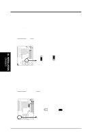
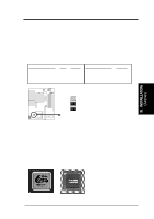
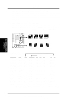
III. INSTALLATION (Jumpers) III. INSTALLATION Jumper Settings 1. Onboard Multi-I/O Selection (JP9) You can selectively disable each onboard Multi-I/O item (floppy, serial, parallel, and IrDA) through Chipset Features Setup of BIOS SOFTWARE or disable all Multi-I/O items at once with the following jumper in order to use your own Multi-I/O card. Selections Enable Disable JP9 [1-2] (Default) [2-3] JP9 1 2 3 Enable (Default) 1 2 3 Disabled Multi I/O Setting (Enable / Disable) JP10 JP9 2. Flash ROM Boot Block Programming (JP10) This sets the operation mode of the boot block area of the Programmable Flash ROM to allow programming in the Enabled position. This is required only if prompted by the Flash Memory Writer Utility as shown in BIOS SOFTWARE. Programming Disabled Enabled JP10 [1-2] (Default) [2-3] JP10 1 2 3 Disabled / Protected (Default) 1 2 3 Enabled Boot Block Programming (Disable / Enable) ASUS P/I-P55TVP4 User's Manual 7
-
 1
1 -
2
-
3
-
4
-
5
-
6
-
7
-
 8
8 -
 9
9 -
 10
10 -
 11
11 -
 12
12 -
 13
13 -
 14
14 -
 15
15 -
 16
16 -
 17
17 -
 18
18 -
19
-
20
-
21
-
22
-
23
-
24
-
25
-
26
-
27
-
28
-
29
-
30
-
31
-
32
-
33
-
34
-
35
-
36
-
37
-
38
-
39
-
40
-
41
-
42
-
43
-
44
-
45
-
46
-
47
-
48
-
49
-
50
-
51
-
52
-
53
-
54
-
55
-
56
-
57
-
58
-
59
-
60
-
61
-
62
-
63
-
64
 |
 |
