Asus P I-P55TVP4 User Manual - Page 17
System Memory DRAM/SDRAM & SRAM
 |
View all Asus P I-P55TVP4 manuals
Add to My Manuals
Save this manual to your list of manuals |
Page 17 highlights
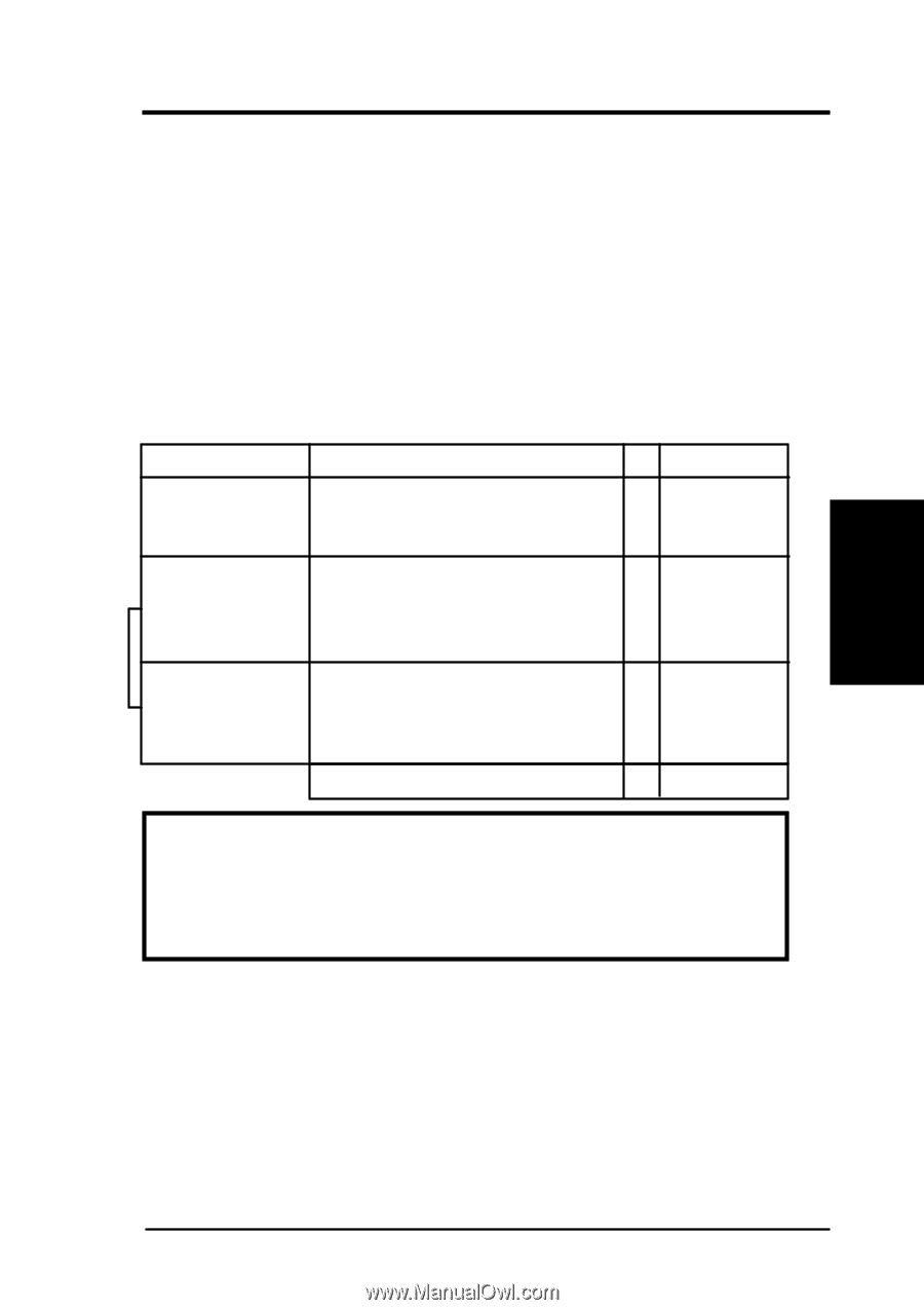
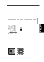
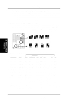
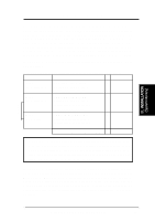
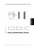
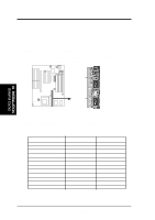
III. INSTALLATION (System Memory) III. INSTALLATION 2. System Memory (DRAM/SDRAM & SRAM) This motherboard supports four 72-pin SIMMs (Single Inline Memory Modules) of 4MB, 8MB, 16MB, or 32MB to form a memory size between 8MB to 128MB. The DRAM can be either 60ns or 70ns Fast Page Mode (Asymmetric or Symmetric) or EDO. SIMMs must be installed in pairs so that each bank contains two of the same size memory modules. A new feature is the support of Dual Inline Memory Modules (DIMM). One slot is available for a 3.3Volt Unbuffered Synchronous DRAM (SDRAM) of either 8, 16, or 32MB. Maximum memory of SIMM + DIMM is 128MB. IMPORTANT: Memory speed setup is required in BIOS Chipset Setup "Auto Configuration." Install memory in any or all of the banks in any combination as follows: Bank Bank 0 SIMM Slots 1&2 Memory Module 4MB, 8MB, 16MB, 32MB 72-pin FPM or EDO SIMM (Single or Double sided) Total Memory x2 Bank 1 4MB, 8MB, 16MB, 32MB x2 SIMM Slots 3&4 72-pin FPM or EDO SIMM (Single sided; or Double but Bank 2 must be empty) Bank 2 8MB, 16MB, 32MB, 64MB x1 DIMM Slot 1 168-pin Synchronous DIMM (Single sided; or Double but Bank 1 must be empty) Total System Memory (Max 128MB) = WARNING: Memory Bank 0 & 1's signal level (not power level) is 5 volts. Memory Bank 2's signal level may be 3.3 volts or 5 volts depending on the SDRAM manufacturer. The SDRAM that you install in the Bank 2 DIMM slot must have 5 volt signal level tolerance when Bank 1 and/or Bank 2 is filled or you may cause damage to the SDRAM. IMPORTANT: Each bank must have the same size memory installed in pairs. Bank 0 can use either Single or Double sided memory modules, independent of Banks 1 & 2. Banks 1&2 are related and combined can only have two sides, either 2 Single sided or 1 Double sided memory module. Do not use memory modules with more than 24 chips per module. Modules with more than 24 chips exceed the design specifications of the memory subsystem and will be unstable. Related ASUS P/I-P55TVP4 User's Manual 11
-
 1
1 -
2
-
3
-
4
-
5
-
6
-
7
-
8
-
9
-
10
-
11
-
 12
12 -
 13
13 -
 14
14 -
 15
15 -
 16
16 -
 17
17 -
 18
18 -
 19
19 -
 20
20 -
 21
21 -
 22
22 -
23
-
24
-
25
-
26
-
27
-
28
-
29
-
30
-
31
-
32
-
33
-
34
-
35
-
36
-
37
-
38
-
39
-
40
-
41
-
42
-
43
-
44
-
45
-
46
-
47
-
48
-
49
-
50
-
51
-
52
-
53
-
54
-
55
-
56
-
57
-
58
-
59
-
60
-
61
-
62
-
63
-
64
 |
 |