Asus P I-P65UP5 C-PKND User Manual - Page 25
SCSI hard drive bootup see HDD Sequence SCSI/IDE First in the BIOS
 |
View all Asus P I-P65UP5 C-PKND manuals
Add to My Manuals
Save this manual to your list of manuals |
Page 25 highlights
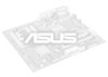
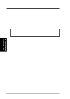
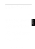
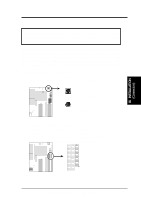
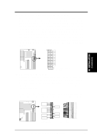
III. INSTALLATION 5. Primary / Secondary IDE connectors (Two 40-pin Block) These connectors support the provided IDE hard disk ribbon cable. After connecting the single end to the board, connect the two plugs at the other end to your hard disk(s). If you install two hard disks on one connector (channel), then you must configure a second drive as Slave mode by setting its jumper according to your hard disk jumper diagram. You may also configure two hard disks to be both Masters using one ribbon cable on the primary IDE connector and another on the secondary IDE connector. A new BIOS feature allows SCSI hard drive bootup (see "HDD Sequence SCSI/IDE First" in the BIOS FEATURES SETUP of the BIOS software). (Pin 20 is removed to prevent inserting in the wrong orientation when using ribbon cables with pin 20 plugged). Pin 1 III. INSTALLATION (Connectors) Secondary IDE Connector Primary IDE Connector 6. Power connector (12-pin block) This connector connects to a standard 5 Volt power supply. To connect the leads from the power supply, ensure first that the power supply is not plugged. Most power supplies provide two plugs (P8 and P9), each containing six wires, two of which are black. Orient the connectors so that the black wires are located in the middle. Using a slight angle, align the plastic guide pins on the lead to their receptacles on the connector. Once aligned, press the lead onto the connector until the lead locks into place. +5V GND +12V PG Power Connector on Motherboard P9 -5V -12V +5V RED RED RED WHT BLK BLK BLK BLK BLU YLW RED ORG P8 Power Plugs from Power Supply ASUS P/I-P65UP5 User's Manual 19
-
 1
1 -
2
-
3
-
4
-
5
-
6
-
7
-
8
-
9
-
10
-
11
-
12
-
13
-
14
-
15
-
16
-
17
-
18
-
19
-
 20
20 -
 21
21 -
 22
22 -
 23
23 -
 24
24 -
 25
25 -
 26
26 -
 27
27 -
 28
28 -
 29
29 -
 30
30 -
31
-
32
 |
 |