Asus P I-XP55TVP4 User Manual - Page 26
Asus P I-XP55TVP4 Manual
 |
View all Asus P I-XP55TVP4 manuals
Add to My Manuals
Save this manual to your list of manuals |
Page 26 highlights
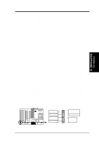
III. INSTALLATION 3. Parallel Printer Connector (25-pin Female) You can enable the parallel port and choose the IRQ through "Onboard Parallel Port" in Chipset Features Setup of the BIOS SOFTWARE. NOTE: Serial printers must be connected to the serial port. Parallel (Printer) Port (25-pin Female) 4. Serial Port COM1 Connector (9-pin Male) The one serial port can be used for pointing devices or other serial devices. The second serial port, COM2, requries a cable and bracket set to connect the onboard connector to an expansion slot opening. Settings can be adjusted through the "Onboard Serial Port" in Chipset Features Setup of the BIOS SOFTWARE. III. INSTALLATION (Connectors) 20 COM 1 5. Universal Serial BUS Ports 1 & 2 (Two 4-pin Female Sockets) Two USB ports are available for connecting USB devices. You must enable the "USB Function" in PNP and PCI Setup of the BIOS SOFTWARE. Universal Serial BUS 1 2 6. Floppy drive connector (34-pin block ) This connector supports the provided floppy drive ribbon cable. After connecting the single end to the board, connect the two plugs on the other end to the floppy drives. (Pin 5 is removed to prevent inserting in the wrong orientation when using ribbon cables with pin 5 plugged). Floppy Drive Connector Pin 1 Floppy Drive Connector ASUS P/I-XP55TVP4 User's Manual
-
 1
1 -
2
-
3
-
4
-
5
-
6
-
7
-
8
-
9
-
10
-
11
-
12
-
13
-
14
-
15
-
16
-
17
-
18
-
19
-
20
-
 21
21 -
 22
22 -
 23
23 -
 24
24 -
 25
25 -
 26
26 -
 27
27 -
 28
28 -
 29
29 -
 30
30 -
 31
31 -
32
 |
 |
