Asus P I-XP55TVP4 User Manual - Page 27
Asus P I-XP55TVP4 Manual
 |
View all Asus P I-XP55TVP4 manuals
Add to My Manuals
Save this manual to your list of manuals |
Page 27 highlights
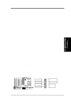
III. INSTALLATION 7. Serial Port COM2 Connector (10-pin block) This connector supports the provided serial port ribbon cable with mounting bracket. Connect the ribbon cable to this connector and mount the bracket to the case on an open slot. The serial port on the mounting bracket will then be used for secondary pointing devices or other serial devices. See "Onboard Serial Port" in Chipset Features Setup of the BIOS SOFTWARE for settings. (Pin 10 is removed to prevent inserting in the wrong orientation when using ribbon cables with pin 10 plugged). Pin 1 COM 2 Onboard Serial Port Connector 8. CPU Cooling Fan Connector (FAN) This connector supports a CPU cooling fan of 500mAMP (6WATT) or less. Orientate the fan so that the heat sink fins allow airflow to go across the onboard heat sink(s) instead of the expansion slots. Depending on the fan manufacturer, the wiring and plug may be different. The red wire should be positive, while the black should be ground. Connect the fan's plug to the board taking into consideration the polarity of the this connector. WARNING: The CPU and/or motherboard will overheat if there is no airflow across the CPU and onboard heatsinks. Damage may occur to the motherboard and/or the CPU fan if these pins are incorrectly used. These are not jumpers, do not place jumper caps over these pins. +12V Air Flow GND Air Flow +12Volt Power Lead for CPU Cooling Fan ASUS P/I-XP55TVP4 User's Manual 21 III. INSTALLATION (Connectors)
-
 1
1 -
2
-
3
-
4
-
5
-
6
-
7
-
8
-
9
-
10
-
11
-
12
-
13
-
14
-
15
-
16
-
17
-
18
-
19
-
20
-
21
-
 22
22 -
 23
23 -
 24
24 -
 25
25 -
 26
26 -
 27
27 -
 28
28 -
 29
29 -
 30
30 -
 31
31 -
 32
32
 |
 |
