Asus P4-P5N9300 User Manual - Page 38
Connectors, Serial ATA connectors 9-pin SATA1, SATA2, COM port connector 10-1pin COM1
 |
View all Asus P4-P5N9300 manuals
Add to My Manuals
Save this manual to your list of manuals |
Page 38 highlights
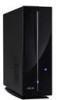
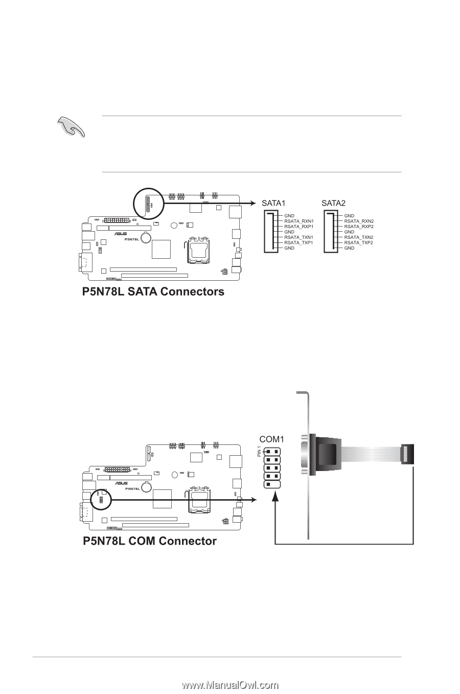
3.4 Connectors 1. Serial ATA connectors (9-pin SATA1, SATA2) These connectors are for the Serial ATA signal cables for Serial ATA hard disk drives. • Install Windows® XP Service Pack 1 before using Serial ATA hard disk drives. • When using the connectors in IDE mode, connect the primary (boot) hard disk drive to the SATA1 or SATA2 connector. 2. COM port connector (10-1pin COM1) This connector is for a serial (COM) port. Connect the serial port module cable to this connector, then install the module to a slot opening at the back of the system chassis. 3-6 Chapter 3: Motherboard info
-
 1
1 -
2
-
3
-
4
-
5
-
6
-
7
-
8
-
9
-
10
-
11
-
12
-
13
-
14
-
15
-
16
-
17
-
18
-
19
-
20
-
21
-
22
-
23
-
24
-
25
-
26
-
27
-
28
-
29
-
30
-
31
-
32
-
 33
33 -
 34
34 -
 35
35 -
 36
36 -
 37
37 -
 38
38 -
 39
39 -
 40
40 -
 41
41 -
 42
42 -
 43
43 -
44
-
45
-
46
-
47
-
48
-
49
-
50
-
51
-
52
-
53
-
54
-
55
-
56
-
57
-
58
-
59
-
60
-
61
-
62
-
63
-
64
-
65
-
66
-
67
-
68
-
69
-
70
-
71
-
72
-
73
-
74
-
75
-
76
-
77
-
78
-
79
-
80
-
81
-
82
 |
 |
3-6
Chapter 3: Motherboard info
3.4
Connectors
1.
Serial ATA connectors (9-pin SATA1, SATA2)
These connectors are for the Serial ATA signal cables for Serial ATA hard disk
drives.
•
Install Windows
®
XP Service Pack 1 before using Serial ATA hard disk
drives.
•
When using the connectors in
IDE mode, connect the primary (boot) hard disk
drive to the SATA1 or SATA2 connector.
2.
COM port connector (10-1pin COM1)
This connector is for a serial (COM) port. Connect the serial port module
cable to this connector, then install the module to a slot opening at the back
of the system chassis.