Asus P4BGL-VM P4BGL-VM User Manual - Page 49
ASUS P4BGL-VM motherboard user guide, Infrared module connector two 5-1 pin IR, GAME/MIDI connector
 |
View all Asus P4BGL-VM manuals
Add to My Manuals
Save this manual to your list of manuals |
Page 49 highlights
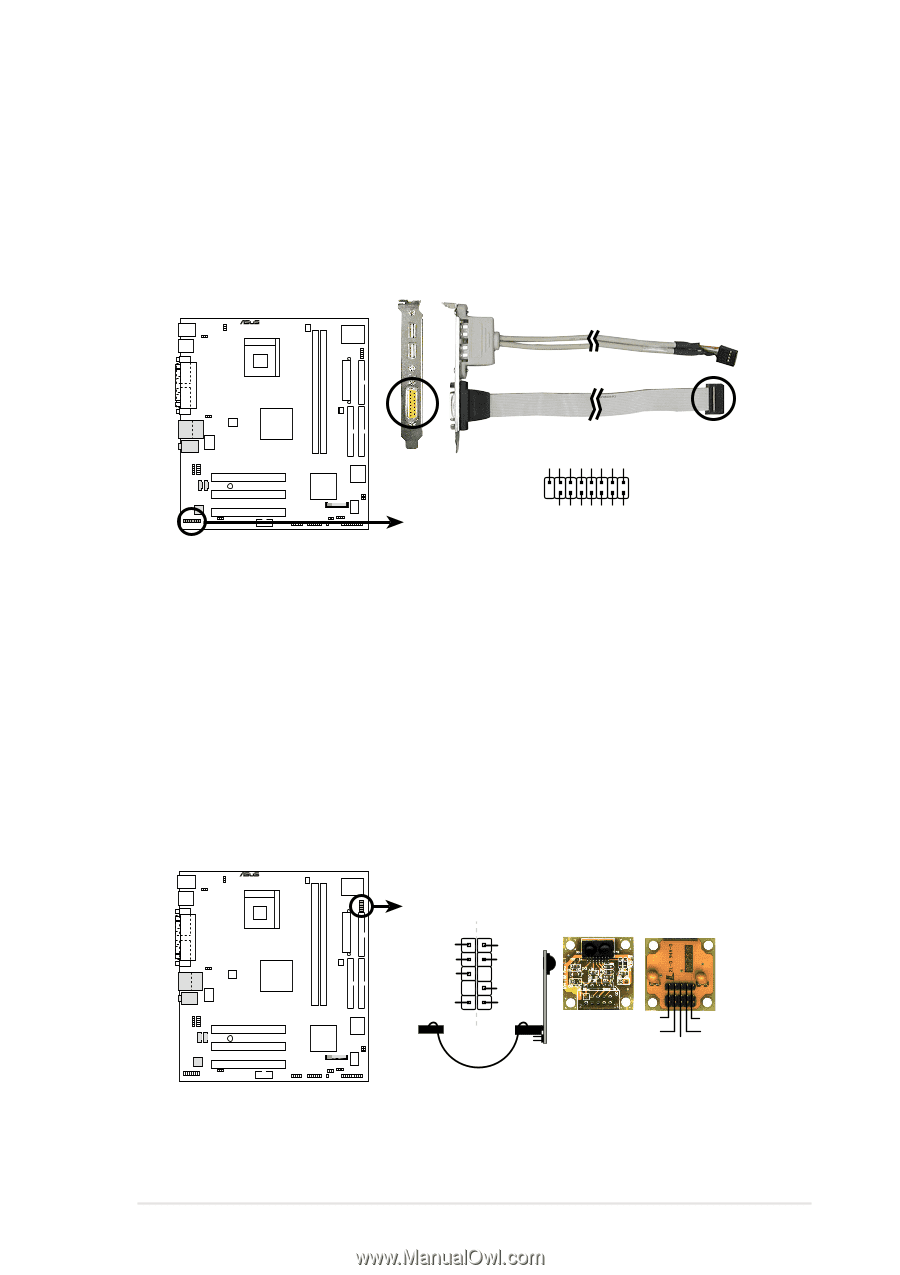
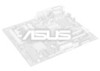
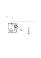
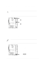
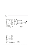
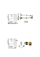
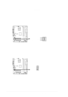
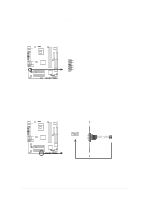
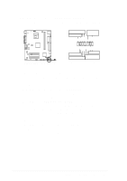
9. GAME/MIDI connector (16-1 pin GAME PORT1) This connector supports a GAME/MIDI module. If your package came with the optional USB 2.0/GAME module, connect the GAME/MIDI cable to this connector. The GAME/MIDI port on the module connects a joystick or a game pad for playing games, and MIDI devices for playing or editing audio files. ® GND J1B2 J1CY GND GND J1CX J1B1 GND P4BGL-VM 8 1 GAME 16 9 P4BGL-VM Game Connector MIDI_IN J2B2 J2CY MIDI_OUT J2CX J2B1 GND 10. Infrared module connector (two 5-1 pin IR) These connectors support an optional wireless transmitting and receiving infrared module. The module mounts to a small opening on system chassis that support this feature. You must also configure the UART2 Use As parameter in BIOS to set UART2 for use with IR. Use the five pins as shown in Back View and connect a ribbon cable from the module to the motherboard SIR connector according to the pin definitions. ® P4BGL-VM SIR CIR IRTX CIR+5V GND CIRRX IRRX GND +5V IRAX Standard Infrared (SIR) Front View Back View IRTX +5V GND (NC) IRRX P4BGL-VM Infrared Module Connector ASUS P4BGL-VM motherboard user guide 2-25
-
 1
1 -
2
-
3
-
4
-
5
-
6
-
7
-
8
-
9
-
10
-
11
-
12
-
13
-
14
-
15
-
16
-
17
-
18
-
19
-
20
-
21
-
22
-
23
-
24
-
25
-
26
-
27
-
28
-
29
-
30
-
31
-
32
-
33
-
34
-
35
-
36
-
37
-
38
-
39
-
40
-
41
-
42
-
43
-
 44
44 -
 45
45 -
 46
46 -
 47
47 -
 48
48 -
 49
49 -
 50
50 -
 51
51 -
 52
52 -
 53
53 -
 54
54 -
55
-
56
-
57
-
58
-
59
-
60
-
61
-
62
-
63
-
64
-
65
-
66
-
67
-
68
-
69
-
70
-
71
-
72
-
73
-
74
-
75
-
76
-
77
-
78
-
79
-
80
-
81
-
82
-
83
-
84
-
85
-
86
-
87
-
88
-
89
-
90
-
91
-
92
-
93
-
94
-
95
-
96
-
97
-
98
-
99
-
100
-
101
-
102
-
103
-
104
-
105
-
106
-
107
-
108
-
109
-
110
-
111
-
112
-
113
-
114
-
115
-
116
-
117
-
118
-
119
-
120
-
121
-
122
-
123
-
124
-
125
-
126
-
127
-
128
-
129
-
130
 |
 |