Asus P4S800 Motherboard DIY Troubleshooting Guide
Asus P4S800 Manual
 |
View all Asus P4S800 manuals
Add to My Manuals
Save this manual to your list of manuals |
Asus P4S800 manual content summary:
- Asus P4S800 | Motherboard DIY Troubleshooting Guide - Page 1
Motherboard P4S800 User Guide - Asus P4S800 | Motherboard DIY Troubleshooting Guide - Page 2
the express written permission of ASUSTeK COMPUTER INC. ("ASUS"). Product warranty or service will not be extended if: (1) the product is AS A COMMITMENT BY ASUS. ASUS ASSUMES NO RESPONSIBILITY OR LIABILITY FOR ANY ERRORS OR INACCURACIES THAT MAY APPEAR IN THIS MANUAL, INCLUDING THE PRODUCTS AND - Asus P4S800 | Motherboard DIY Troubleshooting Guide - Page 3
assignments for this motherboard 1-15 1.11 Jumpers 1-16 1.12 Connectors 1-18 Chapter 2: BIOS information 2.1 Managing and updating your BIOS 2-2 2.1.1 Using ASUS EZ Flash to update the BIOS 2-2 2.1.2 Using AFLASH to update the BIOS 2-3 2.1.3 CrashFree BIOS 2 feature 2-6 2.2 BIOS Setup program - Asus P4S800 | Motherboard DIY Troubleshooting Guide - Page 4
Safeguards Contents 2.2.1 BIOS menu bar 2-7 2.2.2 Legend bar support 3.1 Install an operating system 3-2 3.2 Support CD information 3-2 3.2.1 Running the support CD 3-2 3.2.2 Drivers menu 3-3 3.2.3 Utilities menu 3-3 3.2.4 ASUS Contact Information 3-4 3.3 Software information 3-4 3.3.1 ASUS - Asus P4S800 | Motherboard DIY Troubleshooting Guide - Page 5
and, if not installed and used in accordance with manufacturer's instructions, may cause harmful interference to radio communications. However, there is reception, which can be determined by turning the equipment off and on, the user is encouraged to try to correct the interference by one or more of - Asus P4S800 | Motherboard DIY Troubleshooting Guide - Page 6
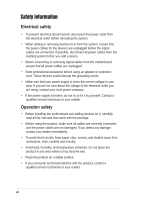
fix it by yourself. Contact a qualified service technician or your retailer. Operation safety • Before installing the motherboard and adding devices on it, carefully read all the manuals If you encounter technical problems with the product, contact a qualified service technician or your retailer. vi - Asus P4S800 | Motherboard DIY Troubleshooting Guide - Page 7
this guide To make sure that you perform certain tasks properly, take note of the following symbols used throughout this manual. WARNING updates. 1. ASUS Websites The ASUS websites worldwide provide updated information on ASUS hardware and software products. The ASUS websites are listed in the ASUS - Asus P4S800 | Motherboard DIY Troubleshooting Guide - Page 8
, CA 94538, USA Fax +1-510-608-4555 E-mail [email protected] Web site usa.asus.com Technical Support Telephone (General) +1-502-995-0883 (Notebook) +1-510-739-3777 Support fax +1-502-933-8713 Support e-mail [email protected] ASUS COMPUTER GmbH (Germany and Austria) Address Harkort Str. 25 - Asus P4S800 | Motherboard DIY Troubleshooting Guide - Page 9
summary CPU Chipset Front Side Bus (FSB) Memory Expansion slots IDE Audio LAN USB 2.0 Special Features Overclocking Features Rear panel I/O Socket 478 for Intel® Pentium® 4 / Celeron processors Supports Intel® Hyper-threading Technology New power design to support Intel® Prescott CPU SiS 648FX SiS - Asus P4S800 | Motherboard DIY Troubleshooting Guide - Page 10
, ASUS CrashFree BIOS 2, ASUS C.P.R. Industry standard PCI 2.2, USB 2.0 Manageability WfM 2.0, DMI 2.0, WOL/WOR by PME, Chassis intrusion, SM bus Form Factor ATX form factor: 12 in x 9.6 in Accessories User's Guide UltraDMA cable FDD cable I/O shield Support CD contents Device drivers ASUS - Asus P4S800 | Motherboard DIY Troubleshooting Guide - Page 11
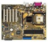
Chapter 1 This chapter describes the features of the P4S800 motherboard. It includes brief descriptions of the motherboard components, and illustrations of the layout, jumper settings, and connectors. Product introduction - Asus P4S800 | Motherboard DIY Troubleshooting Guide - Page 12
technologies making it another standout in the long line of ASUS quality motherboards! The motherboard incorporates the Intel® Pentium® 4 or Celeron Processor in a 478-pin package with Intel® Hyper-Threading Technology support coupled with the SiS® 648FX chipset with Front Side Bus 800 (FSB800 - Asus P4S800 | Motherboard DIY Troubleshooting Guide - Page 13
, learn about its major components and available features to facilitate the installation and future upgrades. Refer to the succeeding pages for the component descriptions. 1 23 4 5 6 16 7 8 15 14 17 13 12 11 10 18 19 27 26 25 24 23 ASUS P4S800 motherboard user guide 9 20 21 22 1-3 - Asus P4S800 | Motherboard DIY Troubleshooting Guide - Page 14
. 3 North bridge controller. The SiS® 648FX provides the processor interface with 800/533/400 MHz frequency, system memory interface at 400/333/266 MHz operation, and AGP 8X interface. 4 DDR DIMM sockets. These three 184-pin DIMM sockets support up to 3GB system memory using unbuffered non-ECC DDR - Asus P4S800 | Motherboard DIY Troubleshooting Guide - Page 15
USB 2.0 devices. 25 Serial port. This 9-pin COM1 port is for pointing devices or other serial devices. 26 S/PDIF jack. This jack connects to external audio output devices. 27 PS/2 keyboard port. This purple connector is for a PS/2 keyboard. ASUS P4S800 motherboard user guide 1-5 - Asus P4S800 | Motherboard DIY Troubleshooting Guide - Page 16
1.4 Special Features 1.4.1 Product highlights With the SiS 648FX chipset, the ASUS P4S800 supports latest 800MHz front side bus and Intel® next generation Prescott CPU. In addition to supporting highbandwidth DDR400, unique MuTIOL technology increases the bus speed between the northbridge and - Asus P4S800 | Motherboard DIY Troubleshooting Guide - Page 17
are separately purchased.) The P4S800 Instant Music Lite feature can only be used on PS/2 keyboards. ASUS EZ Flash With ASUS EZ Flash, you can update BIOS before entering operating system. No more DOS-based flash utility and bootable diskette required. ASUS P4S800 motherboard user guide 1-7 - Asus P4S800 | Motherboard DIY Troubleshooting Guide - Page 18
DIMM3 (64/72 bit,184-pin module) PARALLEL PORT COM1 USB12 USBPW12 USBPW34 Bottom: USB3 USB4 Top: RJ-45 CPU_FAN ATX12V SiS 648FX Chip Top:Line In Center:Line Out Below:Mic In Accelerated Graphics Port (AGP) P4S800 ® PCI1 SiS 963LUA Chipset SPDIF_OUT FP_AUDIO CD AUX Audio Codec PCI2 - Asus P4S800 | Motherboard DIY Troubleshooting Guide - Page 19
damage motherboard components. 1.7.1 Placement direction When installing the motherboard, make sure that you place it into the chassis in the correct orientation. The edge with external ports goes to the rear part of the chassis as indicated in the image below. ASUS P4S800 motherboard user guide - Asus P4S800 | Motherboard DIY Troubleshooting Guide - Page 20
Processing Unit (CPU) 1.8.1 Overview The motherboard comes with a surface mount 478-pin Zero Insertion Force (ZIF) socket. The socket is designed for the Intel® Pentium® 4 Processor in the 478-pin package with 512/256KB L2 cache on 0.13 micron process. This processor supports 800/533/400MHz - Asus P4S800 | Motherboard DIY Troubleshooting Guide - Page 21
to secure the CPU. The lever clicks on the side tab to indicate that it is locked. 6. Install a CPU heatsink and fan following the instructions that came with the heatsink package. 7. Connect the CPU fan cable to the CPU fan connector on the motherboard. ASUS P4S800 motherboard user guide 1-11 - Asus P4S800 | Motherboard DIY Troubleshooting Guide - Page 22
the motherboard and other system components. • When installing long AGP cards, it is recommended to install the memory modules first. Long AGP cards when installed may interfere with memory socket. • Make sure that the memory frequency matches the CPU Front Side Bus. Refer to Table 1.9.1 for details - Asus P4S800 | Motherboard DIY Troubleshooting Guide - Page 23
Vendor List The following table lists the memory modules that have been tested and qualified for use with this motherboard. Qualified DDR 400 memory modules: Vendor Part Number Chip Vendor 512MB 512MB 256MB 512MB 256MB 512MB 256MB 512MB 256MB 512MB 512MB ASUS P4S800 motherboard user guide 1-13 - Asus P4S800 | Motherboard DIY Troubleshooting Guide - Page 24
512MB 512MB 1.10 Expansion slots The motherboard has five PCI slots, one Accelerated Graphics Port slot and the ASUS proprietary Wireless Fidelity (WiFi) slot. To install and configure an expansion card: 1. Install an expansion card following the instructions that came with the chassis. 2. Turn - Asus P4S800 | Motherboard DIY Troubleshooting Guide - Page 25
shared - - - - - When using PCI cards on shared slots, ensure that the drivers support "Share IRQ" or that the cards do not need IRQ assignments. Otherwise, conflicts will arise between the two PCI groups, making the system unstable and the card inoperable. ASUS P4S800 motherboard user guide 1-15 - Asus P4S800 | Motherboard DIY Troubleshooting Guide - Page 26
to wake up from S3 and S4 sleep modes (no power to CPU, DRAM in slow refresh, power supply in reduced power mode). The rear panel USB ports (Ports 1 to 4) do not support device wake-up from S4 sleep mode. P4S800 ® P4S800 USB Device Wake Up USBPW12 USBPW34 12 23 +5V (Default) +5VSB USBPW56 - Asus P4S800 | Motherboard DIY Troubleshooting Guide - Page 27
need to clear the RTC when the system hangs due to overclocking. For system failure due to overclocking, use the C.P.R. (CPU Parameter Recall) feature. Shut down and reboot the system so BIOS can automatically reset parameter settings to its previous state. ASUS P4S800 motherboard user guide 1-17 - Asus P4S800 | Motherboard DIY Troubleshooting Guide - Page 28
motherboard, connect the other end to the floppy drive. (Pin 5 is removed to prevent incorrect insertion when using ribbon cables with pin 5 plug). PIN 1 P4S800 ® FLOPPY NOTE: Orient the red markings on the floppy ribbon cable to PIN 1. P4S800 jumper settings. BIOS supports specific device bootup. - Asus P4S800 | Motherboard DIY Troubleshooting Guide - Page 29
the 20-pin ATXPWR connector, this motherboard requires that you connect the 4-pin ATX +12V power plug to provide sufficient power to the CPU. Make sure that your ATX 12V . CHASSIS +5VSB_MB Chassis Signal GND P4S800 ® P4S800 Chassis Alarm Lead (Default) ASUS P4S800 motherboard user guide 1-19 - Asus P4S800 | Motherboard DIY Troubleshooting Guide - Page 30
flow within the system may damage the motherboard components. These are not jumpers! DO NOT place jumper caps on the fan connectors! CPU_FAN P4S800 ® CHA_FAN Rotation +12V GND P4S800 12-Volt Fan Connectors 6. GAME/MIDI connector (16-1 pin GAME) This connector supports a GAME/MIDI module. Connect an - Asus P4S800 | Motherboard DIY Troubleshooting Guide - Page 31
5VA BLINE_OUT_R BLINE_OUT_L P4S800 ® FP_AUDIO MIC2 MICPWR Line out_R NC Line out_L P4S800 Front Panel Audio Connector 9. WiFi connector (63-pin WIFI) This slot supports the ASUS proprietary WiFi (Wireless Fidelity) module. P4S800 ® P4S800 Wi-Fi Slot ASUS P4S800 motherboard user guide WIFI 1-21 - Asus P4S800 | Motherboard DIY Troubleshooting Guide - Page 32
2.0 specification that supports up sound output. If the S/PDIF out port at the rear panel is inadequate use this to connect one end of the audio cable to the S/PDIF_OUT connector on the motherboard, and the other end to the S/PDIF module. SPDIF_OUT P4S800 ® +5V SPDIFOUT GND P4S800 Digital Audio - Asus P4S800 | Motherboard DIY Troubleshooting Guide - Page 33
hear system beeps and warnings. • System Management Interrupt Lead (2-pin SMI) This 2-pin connector allows you to manually place the between ON and SLEEP, or ON and SOFT OFF, depending on the BIOS or OS settings. Pressing the power switch while in the ON mode ASUS P4S800 motherboard user guide 1-23 - Asus P4S800 | Motherboard DIY Troubleshooting Guide - Page 34
1-24 Chapter 1: Product introduction - Asus P4S800 | Motherboard DIY Troubleshooting Guide - Page 35
Chapter 2 This chapter tells how to change system settings through the BIOS Setup menus. Detailed descriptions of the BIOS parameters are also provided. BIOS information - Asus P4S800 | Motherboard DIY Troubleshooting Guide - Page 36
save a copy of the motherboard's original BIOS to a bootable floppy disk in case you need to reinstall the original BIOS later. 2.1.1 Using ASUS EZ Flash to update the BIOS The ASUS EZ Flash feature allows you to easily update the BIOS without having to go through the long process of booting from - Asus P4S800 | Motherboard DIY Troubleshooting Guide - Page 37
work with certain memory drivers that may be loaded when you boot from the hard drive. It is recommended that you reboot using a floppy disk. 3. Reboot the computer from the floppy disk. BIOS setup must specify "Floppy" as the first item in the boot sequence. ASUS P4S800 motherboard user guide 2-3 - Asus P4S800 | Motherboard DIY Troubleshooting Guide - Page 38
result to more problems with the motherboard! 1. Download an updated ASUS BIOS file from the Internet (WWW or FTP) (see ASUS CONTACT INFORMATION on page viii for details) and save to the boot floppy disk you created earlier. 2. Boot from the floppy disk. 3. At the "A:\" prompt, type AFLASH and then - Asus P4S800 | Motherboard DIY Troubleshooting Guide - Page 39
The boot block is updated automatically only when necessary. This minimizes the possibility of boot problems in case of update failures. When the programming is done, the message "Flashed Successfully" appears. 8. Follow the onscreen instructions to continue. ASUS P4S800 motherboard user guide 2-5 - Asus P4S800 | Motherboard DIY Troubleshooting Guide - Page 40
if the problem persists, load the original BIOS file you saved to the boot disk. If the Flash Memory Writer utility is not able to successfully update a complete BIOS file, the system may not boot. If this happens, call the ASUS service center for support. 2.1.3 CrashFree BIOS 2 (BIOS Auto-recovery - Asus P4S800 | Motherboard DIY Troubleshooting Guide - Page 41
motherboard supports a programmable Flash ROM that you can update using the provided utility described in section "2.1 Managing and updating your BIOS." Use the BIOS Setup program when you are installing a motherboard until the desired item is highlighted. ASUS P4S800 motherboard user guide 2-7 - Asus P4S800 | Motherboard DIY Troubleshooting Guide - Page 42
changes and exits Setup General help In addition to the Item Specific Help window, the BIOS setup program also provides a General Help screen. You may launch for detailed information on saving changes and exiting the setup program. Scroll bar When a scroll bar appears to the right of a help window, - Asus P4S800 | Motherboard DIY Troubleshooting Guide - Page 43
88M, 3.5 in.] Floppy 3 Mode Support [Disabled] This is required to support older Japanese floppy drives. The Floppy 3 Mode feature allows reading and writing of 1.2MB (as opposed to 1.44MB) on a 3.5-inch diskette. Configuration options: [Disabled] [Enabled] ASUS P4S800 motherboard user guide 2-9 - Asus P4S800 | Motherboard DIY Troubleshooting Guide - Page 44
to section "Clear RTC RAM" on how to clear the RTC RAM. Halt On [All Errors] This field specifies the types of errors that will cause the system to halt. Configuration options: [All Errors] [No Error] [All but Keyboard] [All but Disk] [All but Disk/Keyboard] Installed Memory [XXX MB] This field - Asus P4S800 | Motherboard DIY Troubleshooting Guide - Page 45
detect incorrect parameters. In these cases, select [User Type HDD] to manually enter the IDE hard disk drive parameters. Refer to the next section for details. Before attempting to configure a hard disk the size for the hard disk drive that you configured. ASUS P4S800 motherboard user guide 2-11 - Asus P4S800 | Motherboard DIY Troubleshooting Guide - Page 46
Select the hard disk drive type in this field. When Logical Block Addressing (LBA) is enabled, the 28-bit addressing of the hard drive Type field to [User Type HDD] and the Translation Method field to [Manual]. CHS Capacity This field shows the drive's maximum CHS capacity as calculated by the BIOS - Asus P4S800 | Motherboard DIY Troubleshooting Guide - Page 47
] to suppress Ultra DMA capability. To make changes to this field, set the Type field to [User Type HDD]. Configuration options: [0] [1] [2] [3] [4] [5] [6] [Disabled] 2.3.2 Keyboard options: [1/4 Sec] [1/2 Sec] [3/4 Sec] [1 Sec] 2.4 Advanced Menu ASUS P4S800 motherboard user guide 2-13 - Asus P4S800 | Motherboard DIY Troubleshooting Guide - Page 48
to allow the system to automatically determine the appropriate CPU core voltage. Configuration options: [Auto] [Manual] CPU VCore [1.xxxV] When the CPU VCore Setting parameter above is set to [Manual], the CPU VCore item allows you to select a specific CPU core voltage. This field is not accessible - Asus P4S800 | Motherboard DIY Troubleshooting Guide - Page 49
BIOS reserves IRQ12, whether or not a PS/2 mouse is detected at startup. Configuration options: [Enabled] [Auto] USB Legacy Support [Auto] This motherboard supports Onboard Memory > ASUS CDROM] This item displays the detected CD-ROM installed in the system. ASUS P4S800 motherboard user guide 2-15 - Asus P4S800 | Motherboard DIY Troubleshooting Guide - Page 50
items 2-5, depending on the memory modules that you are using. memory module stores critical information about the module, such as memory type, size, speed, voltage interface, and module banks. Configuration options: [User [9T] Chipset Clock Mode [Synchronous] This item sets the chipset clock mode. - Asus P4S800 | Motherboard DIY Troubleshooting Guide - Page 51
Memory Cache Mode [UC] USWC (uncacheable, speculative write combining) is a new cache technology for the video memory Support [Enabled] This item controls the IDE Bus Master support for non-Windows operating systems. Configuration options: [Disabled] [Enabled] ASUS P4S800 motherboard user guide - Asus P4S800 | Motherboard DIY Troubleshooting Guide - Page 52
] [200H-207H] [208H-20FH] Onboard MIDI I/O [Disabled] This field sets the I/O address for the MIDI I/O port. Configuration options: [Disabled] [330H-331H] [300H-301H] 2-18 Chapter 2: BIOS information - Asus P4S800 | Motherboard DIY Troubleshooting Guide - Page 53
properly. Setting this field to [Enabled] corrects this problem. If you are using standard VGA cards, leave this default setting [32] for best performance and stability. Primary VGA BIOS [PCI VGA Card] This field allows you to select the Disabled] [Enabled] ASUS P4S800 motherboard user guide 2-19 - Asus P4S800 | Motherboard DIY Troubleshooting Guide - Page 54
ROM. Configuration options: [Disabled] [Enabled] Onboard AC97 Audio Controller [Auto] This field allows you to disable the onboard AC97 audio controller or set to the default [Auto] for optimum device that requires a unique IRQ. Configuration options: [No/ICU] [Yes] 2-20 Chapter 2: BIOS information - Asus P4S800 | Motherboard DIY Troubleshooting Guide - Page 55
To RAM [Disabled] This field allows you to enable or disable the ACPI Suspend-to-RAM feature. To support this feature, the +5VSB of the power supply should have the capacity to provide more than 720mA current. Configuration options: [Disabled] [Enabled] ASUS P4S800 motherboard user guide 2-21 - Asus P4S800 | Motherboard DIY Troubleshooting Guide - Page 56
or modem card. This feature requires an ATX power supply that provides at least 1A on the +5VSB lead. Configuration options: [Disabled] [Enabled] 2-22 Chapter 2: BIOS information - Asus P4S800 | Motherboard DIY Troubleshooting Guide - Page 57
the onboard voltage regulators. If any of the monitored items is out of range, the following error message appears: "Hardware Monitor found an error. Enter Power setup menu for details". And be prompted to "Press F1 to continue or DEL to enter SETUP". ASUS P4S800 motherboard user guide 2-23 - Asus P4S800 | Motherboard DIY Troubleshooting Guide - Page 58
among the four possible types of boot devices listed Configuration fields include Removable Devices, IDE Hard Drive, ATAPI CD-ROM, and Other Boot Device. Removable Device [Legacy PnP) to configure the PCI bus slots instead of using the BIOS. When [Yes] is selected, interrupts may be reassigned by the - Asus P4S800 | Motherboard DIY Troubleshooting Guide - Page 59
Configuration options: [Disabled] [Enabled] Boot Up Floppy Seek [Enabled] When enabled, the BIOS will seek the floppy disk drive to determine whether the drive has 40 or 80 appears only if you installed an Intel Pentium 4 CPU that supports this feature. ASUS P4S800 motherboard user guide 2-25 - Asus P4S800 | Motherboard DIY Troubleshooting Guide - Page 60
saves your selections without exiting the Setup program. You can then return to other menus and make further changes. After you select this option, a confirmation window appears. Select [Yes] to save changes to the non-volatile RAM. 2-26 Chapter 2: BIOS information - Asus P4S800 | Motherboard DIY Troubleshooting Guide - Page 61
Chapter 3 This chapter describes the contents of the support CD that comes with the motherboard package. Software support - Asus P4S800 | Motherboard DIY Troubleshooting Guide - Page 62
utility drivers that enhance the motherboard features. The contents of the support CD are subject to change at any time without notice. Visit the ASUS website for updates. 3.2.1 Running the support CD To begin using the support CD, simply insert the CD into your CD-ROM drive. The CD automatically - Asus P4S800 | Motherboard DIY Troubleshooting Guide - Page 63
the SiS Fast Ethernet network driver. USB 2.0 Driver This item installs the USB 2.0 driver. • The USB 2.0 driver is only supported in Windows 2000. • Windows XP users must install USB 2.0 driver with Win XP SP1 • This motherboard does not support USB 2.0 drivers under Windows 98 or Windows ME - Asus P4S800 | Motherboard DIY Troubleshooting Guide - Page 64
program allows you to download the latest version of the BIOS from the ASUS website. Before using the ASUS Update, make sure that you have an Internet connection so you can connect to the ASUS website. Microsoft DirectX Driver This item installs the Microsoft DirectX driver. Anti-virus Utility The - Asus P4S800 | Motherboard DIY Troubleshooting Guide - Page 65
using the power switch. 4. If the system lost connection or did not detect any optical drive, the Instant Music Lite feature turns OFF (disabled) automatically. A "beep" indicates this condition. ASUS P4S800 motherboard user guide 3-5 - Asus P4S800 | Motherboard DIY Troubleshooting Guide - Page 66
on your keyboard to play audio CDs. These keys only function as indicated if you enabled the Instant Music Lite in BIOS. Instant Music function keys (Set 1) CD ON/OFF Esc PLAY/PAUSE once to stop playing the CD. Press F2 or Enter one more time to eject the CD. 3-6 Chapter 3: Software support
-
 1
1 -
 2
2 -
 3
3 -
 4
4 -
 5
5 -
 6
6 -
 7
7 -
8
-
9
-
10
-
11
-
12
-
13
-
14
-
15
-
16
-
17
-
18
-
19
-
20
-
21
-
22
-
23
-
24
-
25
-
26
-
27
-
28
-
29
-
30
-
31
-
32
-
33
-
34
-
35
-
36
-
37
-
38
-
39
-
40
-
41
-
42
-
43
-
44
-
45
-
46
-
47
-
48
-
49
-
50
-
51
-
52
-
53
-
54
-
55
-
56
-
57
-
58
-
59
-
60
-
61
-
62
-
63
-
64
-
65
-
66
 |
 |

Motherboard
P4S800
User Guide