Asus P4S800 Motherboard DIY Troubleshooting Guide - Page 14
Product introduction - bios
 |
View all Asus P4S800 manuals
Add to My Manuals
Save this manual to your list of manuals |
Page 14 highlights
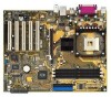
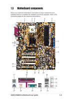
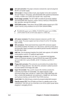
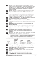
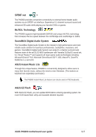
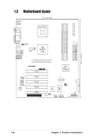
1 ATX 12V connector. This power connector connects the 4-pin 12V plug from the ATX 12V power supply. 2 CPU socket. A 478-pin surface mount, Zero Insertion Force (ZIF) socket for the Intel® Pentium® 4 Processor, with 800/533/400 MHz system bus that allows 6.4GB/s, 4.3GB/s and 3.2GB/s data transfer rates, respectively. 3 North bridge controller. The SiS® 648FX provides the processor interface with 800/533/400 MHz frequency, system memory interface at 400/333/266 MHz operation, and AGP 8X interface. 4 DDR DIMM sockets. These three 184-pin DIMM sockets support up to 3GB system memory using unbuffered non-ECC DDR SDRAM DIMMs. PC2100/1600 support up to 3 DIMMs; PC3200/2700 support up to 2 DIMMs; 1 GB PC3200/2700 with 32 DDR chips support to 1 DIMM only. 5 ATX power connector. This 20-pin connector connects to an ATX +12V power supply. The power supply must have at least 1A on the +5V standby lead (+5VSB). 6 IDE connectors. These dual-channel bus master IDE connectors support Ultra DMA133/100/66, PIO Modes 3 & 4 IDE devices. Both the primary (blue) and secondary (black) connectors are slotted to prevent incorrect insertion of the IDE ribbon cable. 7 AGP slot. This Accelerated Graphics Port (AGP) slot supports 1.5V AGP8X mode graphics cards for 3D graphical applications. 8 South bridge controller. The SiS® 963L is a subsystem that integrates various I/O functions including 2-channel ATA133 bus master IDE controller, up to six USB 2.0/1.1 ports, I/O APIC, AC'97 2.2 interface, and PCI 2.2 interface. 9 Floppy disk connector. This connector accommodates the provided ribbon cable for the floppy disk drive. One side of the connector is slotted to prevent incorrect insertion of the floppy disk cable. 10 Super I/O controller. This Low Pin Count (LPC) interface provides the commonly used Super I/O functionality. The chipset supports a highperformance floppy disk controller for a 360K/720K/1.44M/2.88M floppy disk drive, a multi-mode parallel port, two serial ports, a GAME port, the mouse and keyboard interface and the BIOS Flash ROM interface. 11 Flash ROM. This 2Mb firmware contains the programmable BIOS program. 12 Standby power LED. This LED lights up if there is a standby power on the motherboard. This LED acts as a reminder to turn off the system power before plugging or unplugging devices. 1-4 Chapter 1: Product introduction
-
 1
1 -
2
-
3
-
4
-
5
-
6
-
7
-
8
-
 9
9 -
 10
10 -
 11
11 -
 12
12 -
 13
13 -
 14
14 -
 15
15 -
 16
16 -
 17
17 -
 18
18 -
 19
19 -
20
-
21
-
22
-
23
-
24
-
25
-
26
-
27
-
28
-
29
-
30
-
31
-
32
-
33
-
34
-
35
-
36
-
37
-
38
-
39
-
40
-
41
-
42
-
43
-
44
-
45
-
46
-
47
-
48
-
49
-
50
-
51
-
52
-
53
-
54
-
55
-
56
-
57
-
58
-
59
-
60
-
61
-
62
-
63
-
64
-
65
-
66
 |
 |