Asus P4SDX P4SDX English Manual Version E1215 - Page 21
System memory
 |
View all Asus P4SDX manuals
Add to My Manuals
Save this manual to your list of manuals |
Page 21 highlights
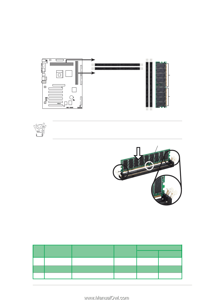
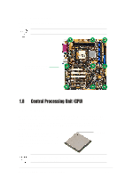
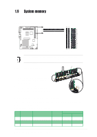
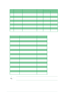
1.9 System memory 1.9.1 Overview The motherboard has four (4) Double Data Rate (DDR) DIMM sockets sockets that supports up to 4GB non-ECC PC2700/2100/1600 DDR. (CHANNEL1) 104 Pins 80 Pins P4SDX ® P4SDX 184-Pin DDR DIMM Sockets (CHANNEL0) Make sure to unplug the power supply before adding or removing DIMMs or other system components. Failure to do so may cause severe damage to the motherboard and other system components. Follow these steps to install a DIMM. DDR DIMM notch 1. Unlock a DIMM socket by pressing the retaining clips outward. 2. Align a DIMM on the socket such that the notch on the DIMM matches the break on the socket. Unlocked Retaining Clip 3. Firmly insert the DIMM into the socket until the retaining clips snap back in place and the DIMM is properly seated. 1.9.2 DIMM Qualified Vendor List The following table lists the memory modules that have been tested and qualified for use with this motherboard. Qualified DDR 400 memory modules: Type Vendor Model Max DIMMs support Size Channel A Channel B SS TwinMOS TMD7608F8E50B 256MB x 2 x 2 SS Apacer K4H560838D-TCC4 256MB x 2 x 2 DS Apacer K4H560838D-TCC4 512MB x 2 x 2 ASUS P4SDX motherboard user guide 1-11
-
 1
1 -
2
-
3
-
4
-
5
-
6
-
7
-
8
-
9
-
10
-
11
-
12
-
13
-
14
-
15
-
 16
16 -
 17
17 -
 18
18 -
 19
19 -
 20
20 -
 21
21 -
 22
22 -
 23
23 -
 24
24 -
 25
25 -
 26
26 -
27
-
28
-
29
-
30
-
31
-
32
-
33
-
34
-
35
-
36
-
37
-
38
-
39
-
40
-
41
-
42
-
43
-
44
-
45
-
46
-
47
-
48
-
49
-
50
-
51
-
52
-
53
-
54
-
55
-
56
-
57
-
58
-
59
-
60
-
61
-
62
-
63
-
64
 |
 |