Asus P5E-VM SE User Manual - Page 45
IEEE 1394a port connector 10-1 pin IE1394_2, Optical drive audio connector 4-pin CD
 |
View all Asus P5E-VM SE manuals
Add to My Manuals
Save this manual to your list of manuals |
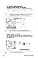
Page 45 highlights
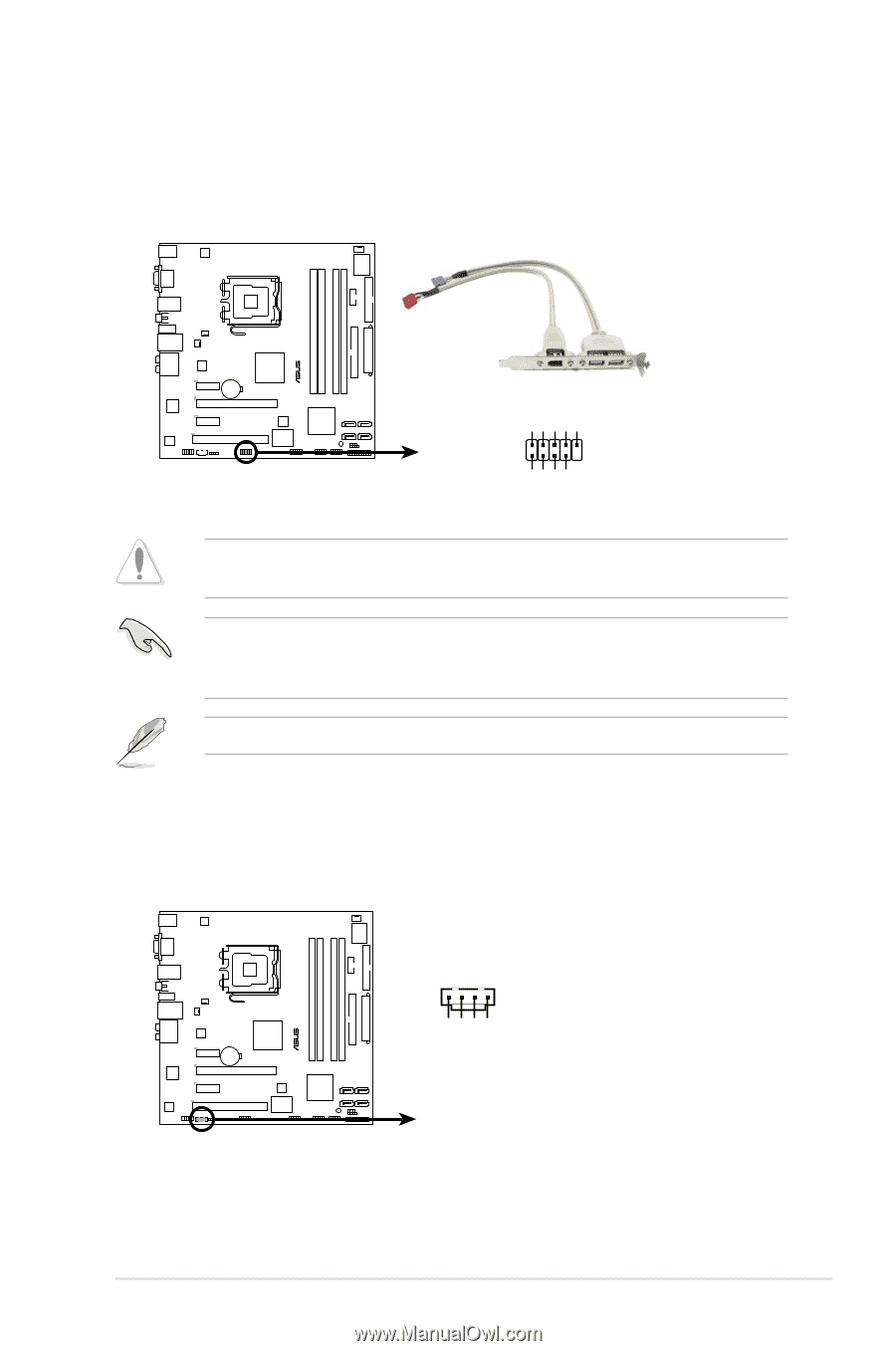
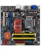
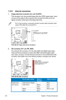
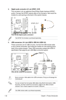
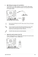
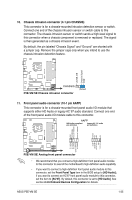
6. IEEE 1394a port connector (10-1 pin IE1394_2) This connector is for a IEEE 1394a port. Connect the IEEE 1394a module cable to this connector, then install the module to a slot opening at the back of the system chassis. ® P5E-VM SE TPA2GND TPB2+12V GND TPA2+ GND TPB2+ +12V IE1394_2 PIN1 P5E-VM SE IEEE 1394a connector Never connect a USB cable to the IEEE 1394a connector. Doing so will damage the motherboard! You can connect the front panel 1394 cable to the ASUS Q-Connector (1394, red) first, and then install the Q-Connector (1394) to the 1394 connector onboard if your chassis supports front panel 1394 ports. The IEEE 1394a module cable is purchased separately. 7. Optical drive audio connector (4-pin CD) These connectors allow you to receive stereo audio input from sound sources such as a CD-ROM, TV tuner, or MPEG card. CD ® P5E-VM SE Left Audio Channel Ground Ground Right Audio Channel P5E-VM SE Internal audio connector ASUS P5E-VM SE 1-33
-
 1
1 -
2
-
3
-
4
-
5
-
6
-
7
-
8
-
9
-
10
-
11
-
12
-
13
-
14
-
15
-
16
-
17
-
18
-
19
-
20
-
21
-
22
-
23
-
24
-
25
-
26
-
27
-
28
-
29
-
30
-
31
-
32
-
33
-
34
-
35
-
36
-
37
-
38
-
39
-
 40
40 -
 41
41 -
 42
42 -
 43
43 -
 44
44 -
 45
45 -
 46
46 -
 47
47 -
 48
48 -
 49
49 -
 50
50 -
51
-
52
-
53
-
54
-
55
-
56
-
57
-
58
-
59
-
60
-
61
-
62
-
63
-
64
-
65
-
66
-
67
-
68
-
69
-
70
-
71
-
72
-
73
-
74
-
75
-
76
-
77
-
78
-
79
-
80
-
81
-
82
-
83
-
84
-
85
-
86
-
87
-
88
-
89
-
90
-
91
-
92
-
93
-
94
-
95
-
96
-
97
-
98
-
99
-
100
-
101
-
102
 |
 |