Asus P5G41T-M LX3 User Manual - Page 33
P5G41T-M LX3 Digital audio connector
 |
View all Asus P5G41T-M LX3 manuals
Add to My Manuals
Save this manual to your list of manuals |
Page 33 highlights
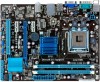
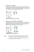
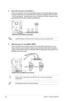
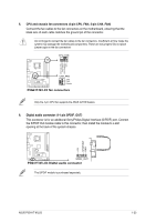
5. CPU and chassis fan connectors (4-pin CPU_FAN, 3-pin CHA_FAN) Connect the fan cables to the fan connectors on the motherboard, ensuring that the black wire of each cable matches the ground pin of the connector. Do not forget to connect the fan cables to the fan connectors. Insufficient air flow inside the system may damage the motherboard components. These are not jumpers! Do not place jumper caps on the fan connectors! CPU_FAN CPU FAN PWM CPU FAN IN CPU FAN PWR GND P5G41T-M LX3 CHA_FAN GND +12V Rotation P5G41T-M LX3 fan connectors Only the 4-pin CPU fan supports the ASUS Q-FAN feature. 6. Digital audio connector (4-1 pin SPDIF_OUT) This connector is for an additional Sony/Philips Digital Interface (S/PDIF) port. Connect the S/PDIF Out module cable to this connector, then install the module to a slot opening at the back of the system chassis. +5V SPDIFOUT GND P5G41T-M LX3 SPDIF_OUT P5G41T-M LX3 Digital audio connector The S/PDIF module is purchased separately. ASUS P5G41T-M LX3 1-23
-
 1
1 -
2
-
3
-
4
-
5
-
6
-
7
-
8
-
9
-
10
-
11
-
12
-
13
-
14
-
15
-
16
-
17
-
18
-
19
-
20
-
21
-
22
-
23
-
24
-
25
-
26
-
27
-
 28
28 -
 29
29 -
 30
30 -
 31
31 -
 32
32 -
 33
33 -
 34
34 -
 35
35 -
 36
36 -
 37
37 -
 38
38 -
39
-
40
-
41
-
42
-
43
-
44
-
45
-
46
-
47
-
48
-
49
-
50
-
51
-
52
-
53
-
54
-
55
-
56
-
57
-
58
-
59
-
60
 |
 |
