Asus P5GD1 P5GD1 User's Manual English Version E1673 - Page 46
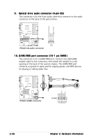
Serial ATA Master/Slave connectors
 |
View all Asus P5GD1 manuals
Add to My Manuals
Save this manual to your list of manuals |
Page 46 highlights
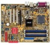
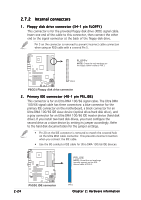
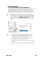
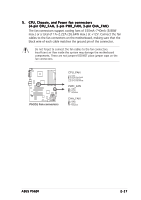
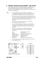
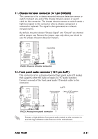
4. Serial ATA connectors (7-pin SATA1, SATA2, SATA3, SATA4) These connectors are for the Serial ATA signal cables for Serial ATA hard disk drives. If you installed Serial ATA hard disk drives, you can can create a RAID 0 or RAID 1 configuration with the Intel® Matrix Storage Technology through the onboard Intel® ICH6R RAID controller. Refer to Chapter 5 for information on creating a RAID configuration. These connectors are set to Standard IDE configuration by default. In Standard IDE mode, you can connect Serial ATA boot/data hard disk drives to these connectors. If you intend to create a Serial ATA RAID set using these connectors, set the C o n f i g u r e S A T A A s item in the BIOS to RAID. See section "4.3.6 IDE Configuration" on page 4-15 for details. P5GD1 P5GD1 SATA connectors SATA2 GND RSATA_TXP2 RSATA_TXN2 GND RSATA_RXN2 RSATA_RXP2 GND SATA1 GND RSATA_TXP1 RSATA_TXN1 GND RSATA_RXN1 RSATA_RXP1 GND SATA4 GND RSATA_TXP4 RSATA_TXN4 GND RSATA_RXN4 RSATA_RXP4 GND SATA3 GND RSATA_TXP3 RSATA_TXN3 GND RSATA_RXN3 RSATA_RXP3 GND Important notes on Serial ATA • These connectors support the Intel® Matrix Storage Technology. • The Serial ATA RAID feature (RAID 0, RAID 1) is available only if you are using Windows® 2000/XP. • Install the Windows® 2000 Service Pack 4 or the Windows® XP Service Pack1 before using Serial ATA. • Use only a maximum of 2 ports for each RAID 0 or RAID 1 set. • Plug your Serial ATA boot disk on the master port (SATA1 and SATA2) to support S3 function. Refer to the table below for details. Serial ATA Master/Slave connectors Connector SATA1, SATA2 SATA3, SATA4 Setting Master Slave Use Boot disk Data disk 2-26 Chapter 2: Hardware information
-
 1
1 -
2
-
3
-
4
-
5
-
6
-
7
-
8
-
9
-
10
-
11
-
12
-
13
-
14
-
15
-
16
-
17
-
18
-
19
-
20
-
21
-
22
-
23
-
24
-
25
-
26
-
27
-
28
-
29
-
30
-
31
-
32
-
33
-
34
-
35
-
36
-
37
-
38
-
39
-
40
-
 41
41 -
 42
42 -
 43
43 -
 44
44 -
 45
45 -
 46
46 -
 47
47 -
 48
48 -
 49
49 -
 50
50 -
 51
51 -
52
-
53
-
54
-
55
-
56
-
57
-
58
-
59
-
60
-
61
-
62
-
63
-
64
-
65
-
66
-
67
-
68
-
69
-
70
-
71
-
72
-
73
-
74
-
75
-
76
-
77
-
78
-
79
-
80
-
81
-
82
-
83
-
84
-
85
-
86
-
87
-
88
-
89
-
90
-
91
-
92
-
93
-
94
-
95
-
96
-
97
-
98
-
99
-
100
-
101
-
102
-
103
-
104
-
105
-
106
-
107
-
108
-
109
-
110
-
111
-
112
-
113
-
114
-
115
-
116
-
117
-
118
-
119
-
120
-
121
-
122
-
123
-
124
-
125
-
126
-
127
-
128
 |
 |