Asus P5KPL-AM User Manual - Page 22
then push the PnP cap from
 |
UPC - 890552664375
View all Asus P5KPL-AM manuals
Add to My Manuals
Save this manual to your list of manuals |
Page 22 highlights
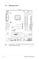
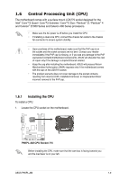
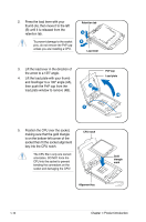
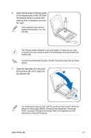
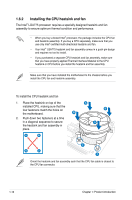
2. Press the load lever with your thumb (A), then move it to the left (B) until it is released from the retention tab. To prevent damage to the socket pins, do not remove the PnP cap unless you are installing a CPU. Retention tab A B Load lever 3. Lift the load lever in the direction of the arrow to a 135º angle. 4. Lift the load plate with your thumb and forefinger to a 100º angle (4A), then push the PnP cap from the 4B load plate window to remove (4B). 3 PnP cap Load plate 4A 5. Position the CPU over the socket, making sure that the gold triangle is on the bottom‑left corner of the socket then fit the socket alignment key into the CPU notch. The CPU fits in only one correct orientation. DO NOT force the CPU into the socket to prevent bending the connectors on the socket and damaging the CPU! CPU notch Alignment key Gold triangle mark 1-10 Chapter 1: Product introduction
-
 1
1 -
2
-
3
-
4
-
5
-
6
-
7
-
8
-
9
-
10
-
11
-
12
-
13
-
14
-
15
-
16
-
 17
17 -
 18
18 -
 19
19 -
 20
20 -
 21
21 -
 22
22 -
 23
23 -
 24
24 -
 25
25 -
 26
26 -
 27
27 -
28
-
29
-
30
-
31
-
32
-
33
-
34
-
35
-
36
-
37
-
38
-
39
-
40
-
41
-
42
-
43
-
44
-
45
-
46
-
47
-
48
-
49
-
50
-
51
-
52
-
53
-
54
-
55
-
56
-
57
-
58
-
59
-
60
-
61
-
62
-
63
-
64
-
65
-
66
-
67
-
68
-
69
-
70
-
71
-
72
-
73
-
74
-
75
-
76
-
77
-
78
-
79
-
80
-
81
-
82
-
83
-
84
-
85
-
86
-
87
-
88
-
89
-
90
 |
 |
