Asus P5ND2 Motherboard Installation Guide - Page 43
pin CPU_FAN, 3-pin PWR_FAN, 3-pin CHA_FAN
 |
View all Asus P5ND2 manuals
Add to My Manuals
Save this manual to your list of manuals |
Page 43 highlights
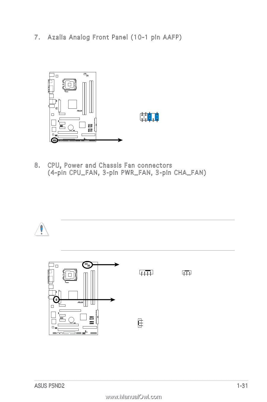
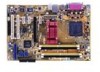
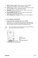
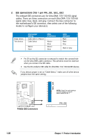
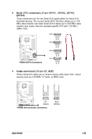
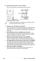
7. Azalia Analog Front Panel (10-1 pin AAFP) This connector is for a chassis-mounted front panel audio I/O module that supports legacy AC '97 audio standard. Connect one end of the front panel audio I/O module cable to this connector. AGND PRESENSE# MIC2_JD HP_HD R P5ND2 AAFP MIC2_L MIC2_R HP_R Jack_Sense HP_L P5ND2 Azalia Analog Front Panel Connector 8. CPU, Power and Chassis Fan connectors (4-pin CPU_FAN, 3-pin PWR_FAN, 3-pin CHA_FAN) The fan connectors support cooling fans of 350 mA ~ 2000 mA (24 W max.) or a total of 1 A ~ 3.48 A (41.76 W max.) at +12V. Connect the fan cables to the fan connectors on the motherboard, making sure that the black wire of each cable matches the ground pin of the connector. Do not forget to connect the fan cables to the fan connectors. Insufficient air flow inside the system may damage the motherboard components. These are not jumpers! Do not place jumper caps on the fan connectors! CPU_FAN PWR_FAN CPU FAN PWM CPU FAN IN CPU FAN PWR GND Rotation +12V GND R P5ND2 P5ND2 Fan Connectors CHA_FAN GND +12V Rotation ASUS P5ND2 1-31
-
 1
1 -
2
-
3
-
4
-
5
-
6
-
7
-
8
-
9
-
10
-
11
-
12
-
13
-
14
-
15
-
16
-
17
-
18
-
19
-
20
-
21
-
22
-
23
-
24
-
25
-
26
-
27
-
28
-
29
-
30
-
31
-
32
-
33
-
34
-
35
-
36
-
37
-
 38
38 -
 39
39 -
 40
40 -
 41
41 -
 42
42 -
 43
43 -
 44
44 -
 45
45 -
 46
46 -
 47
47 -
 48
48 -
49
-
50
-
51
-
52
-
53
-
54
-
55
-
56
-
57
-
58
-
59
-
60
-
61
-
62
-
63
-
64
-
65
-
66
-
67
-
68
-
69
-
70
-
71
-
72
-
73
-
74
-
75
-
76
-
77
-
78
-
79
-
80
-
81
-
82
-
83
-
84
-
85
-
86
-
87
-
88
-
89
-
90
-
91
-
92
-
93
-
94
-
95
-
96
-
97
-
98
-
99
-
100
 |
 |