Asus P5Q WS User Manual - Page 62
G.P. Diagnosis card layout, Installing G.P. Diagnosis card
 |
UPC - 610839162819
View all Asus P5Q WS manuals
Add to My Manuals
Save this manual to your list of manuals |
Page 62 highlights
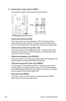
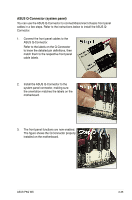
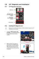
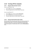
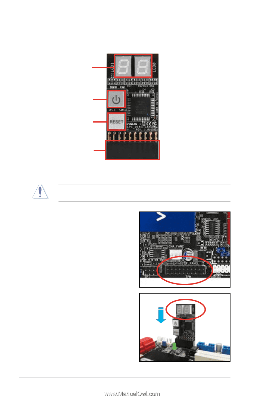
2.8 G.P. Diagnosis card installation 2.8.1 G.P. Diagnosis card layout LED 0 and 1 Power Switch. Press to turn ON or OFF the computer. Reset Button. Press to restart the computer. Card connector 2.8.2 Installing G.P. Diagnosis card Make sure to turn off the power supply unit before instaling the diagnosis card to avoid electrical shock hazard. 1. Locate the TPM connector (20-1 pin TPM) on the motherboard (Refer to page 2-32 for the connector location). 2. With the LEDs of the diagnosis card facing to the DIMM sockets, align the card connector with the TPM connector and press firmly until the card sits on the connector completely. 2-36 Chapter 2: Hardware information
-
 1
1 -
2
-
3
-
4
-
5
-
6
-
7
-
8
-
9
-
10
-
11
-
12
-
13
-
14
-
15
-
16
-
17
-
18
-
19
-
20
-
21
-
22
-
23
-
24
-
25
-
26
-
27
-
28
-
29
-
30
-
31
-
32
-
33
-
34
-
35
-
36
-
37
-
38
-
39
-
40
-
41
-
42
-
43
-
44
-
45
-
46
-
47
-
48
-
49
-
50
-
51
-
52
-
53
-
54
-
55
-
56
-
 57
57 -
 58
58 -
 59
59 -
 60
60 -
 61
61 -
 62
62 -
 63
63 -
 64
64 -
 65
65 -
 66
66 -
 67
67 -
68
-
69
-
70
-
71
-
72
-
73
-
74
-
75
-
76
-
77
-
78
-
79
-
80
-
81
-
82
-
83
-
84
-
85
-
86
-
87
-
88
-
89
-
90
-
91
-
92
-
93
-
94
-
95
-
96
-
97
-
98
-
99
-
100
-
101
-
102
-
103
-
104
-
105
-
106
-
107
-
108
-
109
-
110
-
111
-
112
-
113
-
114
-
115
-
116
-
117
-
118
-
119
-
120
-
121
-
122
-
123
-
124
-
125
-
126
-
127
-
128
-
129
-
130
-
131
-
132
-
133
-
134
-
135
-
136
-
137
-
138
-
139
-
140
-
141
-
142
-
143
-
144
-
145
-
146
-
147
-
148
-
149
-
150
-
151
-
152
-
153
-
154
-
155
-
156
-
157
-
158
-
159
-
160
-
161
-
162
-
163
-
164
-
165
-
166
-
167
-
168
-
169
-
170
-
171
-
172
-
173
-
174
-
175
-
176
 |
 |
2-36
Chapter 2: Hardware information
2.8
G.P. Diagnosis card installation
2.8.1
G.P. Diagnosis card layout
1.
Locate the
TPM connector (20-1
pin TPM)
on the motherboard (Refer
to page 2-32 for the connector
location).
2.
With the LEDs of the diagnosis
card facing to the DIMM sockets,
align the card connector with the
TPM connector and press firmly
until the card sits on the connector
completely.
Make sure to turn off the power supply unit before instaling the diagnosis card to
avoid electrical shock hazard.
2.8.2
Installing G.P. Diagnosis card
LED 0 and 1
Card connector
Power Switch. Press
to turn ON or OFF the
computer.
Reset Button.
Press to restart the
computer.