Asus P5V-X SE User Manual - Page 40
Internal connectors
 |
View all Asus P5V-X SE manuals
Add to My Manuals
Save this manual to your list of manuals |
Page 40 highlights
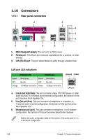
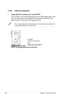
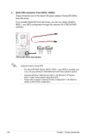
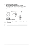
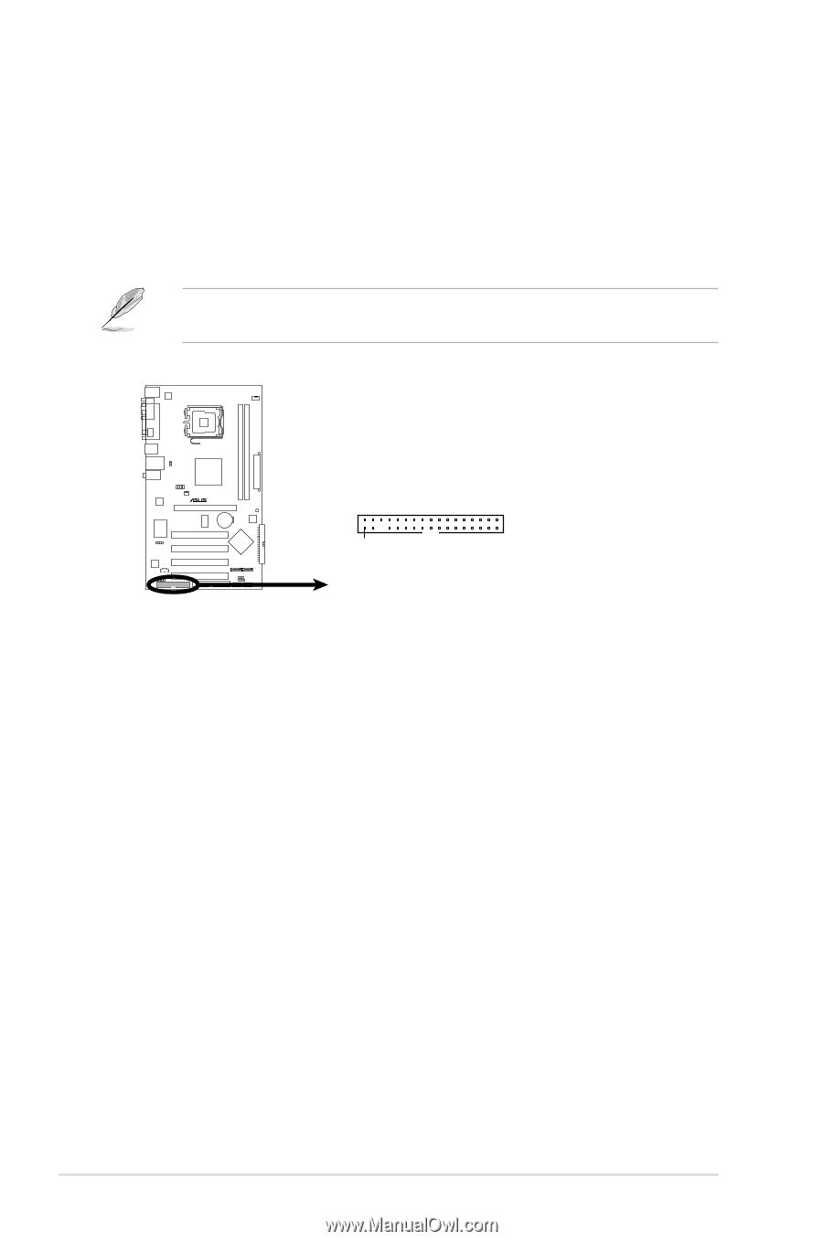
1.10.2 Internal connectors 1. Floppy disk drive connector (34-1 pin FLOPPY) This connector is for the provided floppy disk drive (FDD) signal cable. Insert one end of the cable to this connector, then connect the other end to the signal connector at the back of the floppy disk drive. Pin 5 on the connector is removed to prevent incorrect cable connection when using an FDD cable with a covered Pin 5. FLOPPY PIN 1 NOTE: Orient the red markings on the floppy ribbon cable to PIN 1. P5V-X SE Floppy Disk Drive Connector P5V-X SE 1-28 Chapter 1: Product introduction
-
 1
1 -
2
-
3
-
4
-
5
-
6
-
7
-
8
-
9
-
10
-
11
-
12
-
13
-
14
-
15
-
16
-
17
-
18
-
19
-
20
-
21
-
22
-
23
-
24
-
25
-
26
-
27
-
28
-
29
-
30
-
31
-
32
-
33
-
34
-
 35
35 -
 36
36 -
 37
37 -
 38
38 -
 39
39 -
 40
40 -
 41
41 -
 42
42 -
 43
43 -
 44
44 -
 45
45 -
46
-
47
-
48
-
49
-
50
-
51
-
52
-
53
-
54
-
55
-
56
-
57
-
58
-
59
-
60
-
61
-
62
-
63
-
64
-
65
-
66
-
67
-
68
-
69
-
70
-
71
-
72
-
73
-
74
-
75
-
76
-
77
-
78
-
79
-
80
-
81
-
82
-
83
-
84
-
85
-
86
-
87
-
88
 |
 |
1-28
Chapter 1: Product introduction
1.10.2
Internal connectors
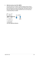
1.
Floppy disk drive connector (34-1 pin FLOPPY)
This connector is for the provided floppy disk drive (FDD) signal cable. Insert
one end of the cable to this connector, then connect the other end to the
signal connector at the back of the floppy disk drive.
Pin 5 on the connector is removed to prevent incorrect cable connection when
using an FDD cable with a covered Pin 5.
P5V-X SE
P5V-X SE
Floppy Disk Drive Connector
NOTE:
Orient the red markings on
the floppy ribbon cable to PIN 1.
PIN 1
FLOPPY