Asus P5V-X SE User Manual - Page 46
Front panel audio connector 10-1 pin AAFP, Speaker connector 4-pin SPEAKER
 |
View all Asus P5V-X SE manuals
Add to My Manuals
Save this manual to your list of manuals |
Page 46 highlights
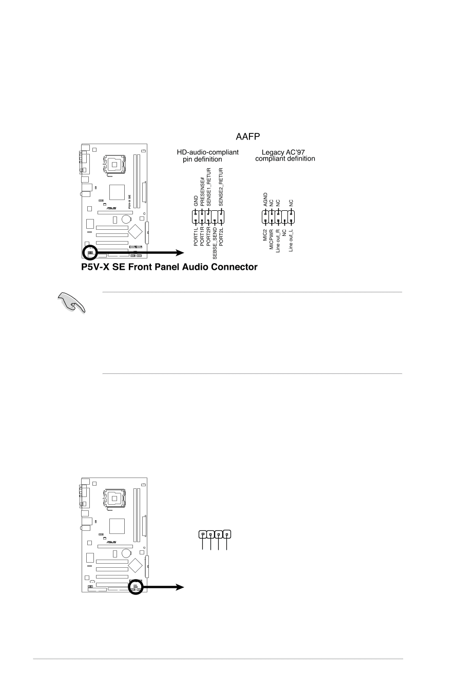
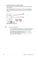
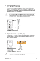
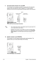
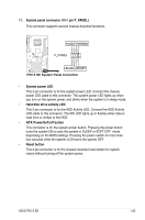
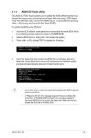
9. Front panel audio connector (10-1 pin AAFP) This connector is for a chassis-mounted front panel audio I/O module that supports either High Definition Audio or legacy AC '97 audio standard. Connect one end of the front panel audio I/O module cable to this connector. • Use a chassis that provides a high-definition audio front panel audio I/O to use the high-definition audio features. • By default, this connector is set to [AC97]. If you want to connect a HighDefinition front panel audio module to this connector, set the Front Panel Support Type item in the BIOS Setup to [HD Audio]. See page 2-22 for details. 10. Speaker connector (4-pin SPEAKER) This connector is for the chassis-mounted system warning speaker. The speaker allows you to hear system beeps and warnings. SPEAKER 1 P5V-X SE +5V GND GND Speaker Out P5V-X SE Speaker Out Connector 1-34 Chapter 1: Product introduction
-
 1
1 -
2
-
3
-
4
-
5
-
6
-
7
-
8
-
9
-
10
-
11
-
12
-
13
-
14
-
15
-
16
-
17
-
18
-
19
-
20
-
21
-
22
-
23
-
24
-
25
-
26
-
27
-
28
-
29
-
30
-
31
-
32
-
33
-
34
-
35
-
36
-
37
-
38
-
39
-
40
-
 41
41 -
 42
42 -
 43
43 -
 44
44 -
 45
45 -
 46
46 -
 47
47 -
 48
48 -
 49
49 -
 50
50 -
 51
51 -
52
-
53
-
54
-
55
-
56
-
57
-
58
-
59
-
60
-
61
-
62
-
63
-
64
-
65
-
66
-
67
-
68
-
69
-
70
-
71
-
72
-
73
-
74
-
75
-
76
-
77
-
78
-
79
-
80
-
81
-
82
-
83
-
84
-
85
-
86
-
87
-
88
 |
 |