Asus P65UP5-P6ND User Manual - Page 15
ASUS P/I-P65UP5 User's Manual, Real Time Clock RTC RAM, Selections, Battery Test Jumper JP9
 |
View all Asus P65UP5-P6ND manuals
Add to My Manuals
Save this manual to your list of manuals |
Page 15 highlights
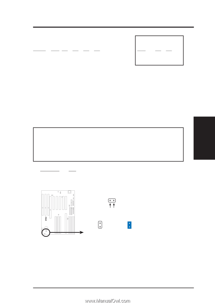
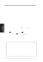
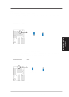
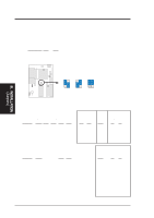
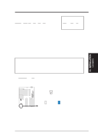
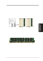
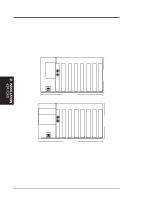
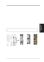
III. INSTALLATION (Jumpers) III. INSTALLATION Intel Pentium II Processor: CPU Internal 266MHz 233MHz BUS (CPU Card BUS Ratio) Ratio JP1 JP2 JP3 JP4 4.0x [short] [short [open] [short] 35x [open] [open] [short] [short] Ext. Freq. 66MHz 66MHz (CPU Ext. Freq on Baseboard) JP3 JP2 [1-2] [2-3] [1-2] [2-3] 4. Real Time Clock (RTC) RAM (JP7) This clears the user-entered information stored in the CMOS RAM of the Real Time Clock such as hard disk information and passwords. To clear the RTC data: (1) Turn off your computer and unplug the AC power, (2) Move this jumper to Clear CMOS, (3) Power on the computer, (4) Turn off the PC, (5) Remove this jumper, (6) Power on the computer, (7) Hold down during bootup and enter BIOS setup to re-enter user preferences. WARNING! You must unplug the power cord to your power supply to ensure that there is no power to your baseboard. The CMOS RAM containing the BIOS setup information may be cleared by this action. You must enter BIOS to "Load Setup Defaults" and re-enter any user information after removing and reapplying this jumper. Selections JP7 Operation [open] (Default) Clear CMOS [short] (momentarily) R RTC RAM JP9 Battery Test JP7 JP7 Operation Open (Default) Clear CMOS Short Battery Test Jumper (JP9) You can test the battery's current by removing the jumper and attaching a current meter to pins 1 and 2. ASUS P/I-P65UP5 User's Manual 15
-
 1
1 -
2
-
3
-
4
-
5
-
6
-
7
-
8
-
9
-
 10
10 -
 11
11 -
 12
12 -
 13
13 -
 14
14 -
 15
15 -
 16
16 -
 17
17 -
 18
18 -
 19
19 -
 20
20 -
21
-
22
-
23
-
24
-
25
-
26
-
27
-
28
-
29
-
30
-
31
-
32
 |
 |