Asus P8H77-M LE P8H77-M LE User's Manual - Page 38
Intel, H77 Serial ATA 3.0Gb/s connectors 7-pin SATA3G_1~4 [blue], USB 2.0 connectors 10-1 pin USB56 - raid
 |
View all Asus P8H77-M LE manuals
Add to My Manuals
Save this manual to your list of manuals |
Page 38 highlights
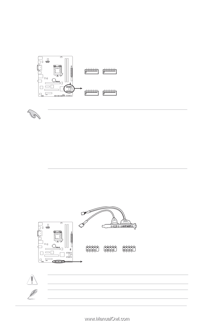
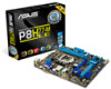
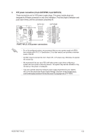
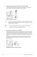
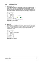
8. Intel® H77 Serial ATA 3.0Gb/s connectors (7-pin SATA3G_1~4 [blue]) These connectors connect to Serial ATA 3.0 Gb/s hard disk drives and optical drives via Serial ATA 3.0 Gb/s signal cables. SATA3G_2 SATA3G_1 GND RSATA_RXP2 RSATA_RXN2 GND RSATA_TXN2 RSATA_TXP2 GND GND RSATA_RXP1 RSATA_RXN1 GND RSATA_TXN1 RSATA_TXP1 GND GND RSATA_RXP4 RSATA_RXN4 GND RSATA_TXN4 RSATA_TXP4 GND GND RSATA_RXP3 RSATA_RXN3 GND RSATA_TXN3 RSATA_TXP3 GND P8H77-M LE SATA3G_4 SATA3G_3 P8H77-M LE Intel® SATA 3.0Gb/s connectors • These connectors are set to [IDE] by default. If you intend to create a Serial ATA RAID set using these connectors, set the SATA Mode Selection item in the BIOS to [RAID]. See section 2.5.3 SATA Configuration for details. • Before creating a RAID set, refer to the RAID Supplementary Guide included in the folder named Manual in the support DVD. • You must install Windows® XP Service Pack 3 or later version before using Serial ATA hard disk drives. The Serial ATA RAID feature (RAID 0, 1, 5, and 10) is available only if you are using Windows® XP SP3 or later version. • When using hot-plug and NCQ, set the SATA Mode Selection item in the BIOS to [AHCI]. See section 2.5.3 SATA Configuration for details. 9. USB 2.0 connectors (10-1 pin USB56, USB78, USB910) These connectors are for USB 2.0 ports. Connect the USB module cable to any of these connectors, then install the module to a slot opening at the back of the system chassis. These USB connectors comply with USB 2.0 specification that supports up to 480 Mbps connection speed. USB910 USB78 USB56 USB+5V USB_P10USB_P10+ GND NC USB+5V USB_P8USB_P8+ GND NC USB+5V USB_P6USB_P6+ GND NC P8H77-M LE PIN 1 USB+5V USB_P9USB_P9+ GND PIN 1 USB+5V USB_P7USB_P7+ GND PIN 1 USB+5V USB_P5USB_P5+ GND P8H77-M LE USB2.0 connector Never connect a 1394 cable to the USB connectors. Doing so will damage the motherboard! The USB module cable is purchased separately. 1-28 Chapter 1: Product introduction
-
 1
1 -
2
-
3
-
4
-
5
-
6
-
7
-
8
-
9
-
10
-
11
-
12
-
13
-
14
-
15
-
16
-
17
-
18
-
19
-
20
-
21
-
22
-
23
-
24
-
25
-
26
-
27
-
28
-
29
-
30
-
31
-
32
-
 33
33 -
 34
34 -
 35
35 -
 36
36 -
 37
37 -
 38
38 -
 39
39 -
 40
40 -
 41
41 -
 42
42 -
 43
43 -
44
-
45
-
46
-
47
-
48
-
49
-
50
-
51
-
52
-
53
-
54
-
55
-
56
-
57
-
58
-
59
-
60
-
61
-
62
-
63
-
64
-
65
-
66
-
67
-
68
-
69
-
70
-
71
-
72
-
73
-
74
-
75
-
76
 |
 |