Asus P8H77-M LE P8H77-M LE User's Manual - Page 39
USB 3.0 connector 20-1 pin USB3_34, Intel, H77 Serial ATA 6.0Gb/s connectors 7-pin SATA6G_1/2 [gray] - le intel h77
 |
View all Asus P8H77-M LE manuals
Add to My Manuals
Save this manual to your list of manuals |
Page 39 highlights
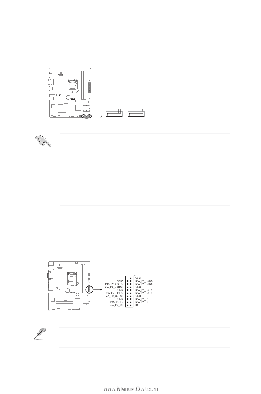
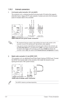
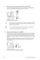
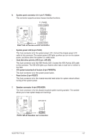
10. Intel® H77 Serial ATA 6.0Gb/s connectors (7-pin SATA6G_1/2 [gray]) These connectors connect to Serial ATA 6.0 Gb/s hard disk drives via Serial ATA 6.0 Gb/s signal cables. GND RSATA_RXP2 RSATA_RXN2 GND RSATA_TXN2 RSATA_TXP2 GND GND RSATA_RXP1 RSATA_RXN1 GND RSATA_TXN1 RSATA_TXP1 GND P8H77-M LE SATA6G_2 SATA6G_1 P8H77-M LE Intel® SATA 6.0Gb/s connectors • These connectors are set to [IDE] by default. If you intend to create a Serial ATA RAID set using these connectors, set the SATA Mode Selection item in the BIOS to [RAID]. See section 2.5.3 SATA Configuration for details. • Before creating a RAID set, refer to the RAID Supplementary Guide included in the folder named Manual in the support DVD. • You must install Windows® XP Service Pack 3 or later version before using Serial ATA hard disk drives. The Serial ATA RAID feature (RAID 0, 1, 5, and 10) is available only if you are using Windows® XP SP3 or later version. • When using hot-plug and NCQ, set the SATA Mode Selection item in the BIOS to [AHCI]. See section 2.5.3 SATA Configuration for details. 11. USB 3.0 connector (20-1 pin USB3_34) This connector is for the additional USB 3.0 ports. Connect the USB 3.0 bracket cable to this connector, then install the USB 3.0 bracket to the rear side of the chassis. If your chassis support customized front panel installation, with ASUS USB 3.0 header, you can have a front panel USB 3.0 solution. USB3_34 P8H77-M LE P8H77-M LE USB3.0 front panel connector • The USB 3.0 module is purchased separately. • Due to Intel® limitations, the USB3_34 only supports Windows® 7 operating system. ASUS P8H77-M LE 1-29
-
 1
1 -
2
-
3
-
4
-
5
-
6
-
7
-
8
-
9
-
10
-
11
-
12
-
13
-
14
-
15
-
16
-
17
-
18
-
19
-
20
-
21
-
22
-
23
-
24
-
25
-
26
-
27
-
28
-
29
-
30
-
31
-
32
-
33
-
 34
34 -
 35
35 -
 36
36 -
 37
37 -
 38
38 -
 39
39 -
 40
40 -
 41
41 -
 42
42 -
 43
43 -
 44
44 -
45
-
46
-
47
-
48
-
49
-
50
-
51
-
52
-
53
-
54
-
55
-
56
-
57
-
58
-
59
-
60
-
61
-
62
-
63
-
64
-
65
-
66
-
67
-
68
-
69
-
70
-
71
-
72
-
73
-
74
-
75
-
76
 |
 |