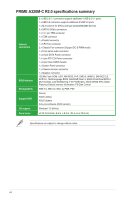
Asus PRIME A320M-C R2.0 User Guide - Page 11
Clear RTC RAM 2-pin CLRTC, To erase the RTC RAM, TPM connector 14-1 pin TPM, M.2 socket 3
 |
View all Asus PRIME A320M-C R2.0 manuals
Add to My Manuals
Save this manual to your list of manuals |
Page 11 highlights
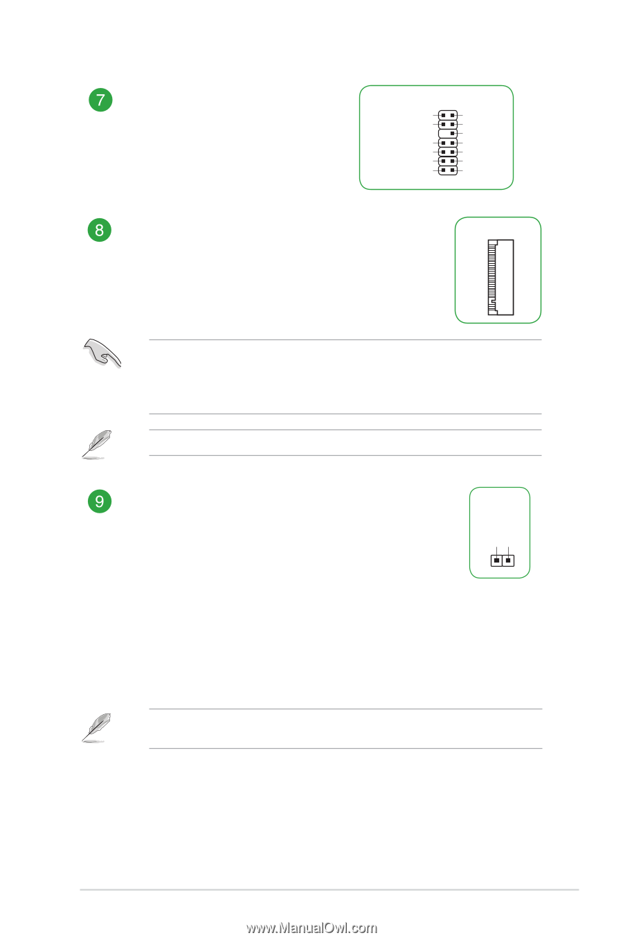
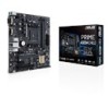
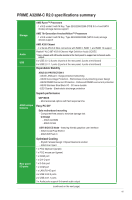
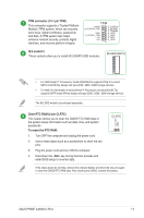
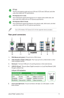
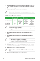
TPM connector (14-1 pin TPM) This connector supports a Trusted Platform Module (TPM) system, which can securely store keys, digital certificates, passwords and data. A TPM system also helps enhance network security, protects digital identities, and ensures platform integrity. TPM +3VSB S_PCIRST#_TBD GND C_PCICLK_TPM +3V +3V F_CLKRUN F_SERIRQ F_FRAME# F_LAD3 F_LAD2 F_LAD1 F_LAD0 PIN 1 M.2 socket 3 These sockets allow you to install M.2 (NGFF) SSD modules. M.2(SOCKET3) • For AMD Ryzen™ Processors, the M.2(SOCKET3) supports PCIE 3.0 x4 and SATA mode M Key design and type 2242 / 2260 / 2280 storage devices. • For AMD 7th Generation A-series/Athlon™ Processors, the M.2(SOCKET3) supports SATA mode M Key design and type 2242 / 2260 / 2280 storage devices. The M.2 SSD module is purchased separately. Clear RTC RAM (2-pin CLRTC) This header allows you to clear the CMOS RTC RAM data of the system setup information such as date, time, and system passwords. To erase the RTC RAM: 1. Turn OFF the computer and unplug the power cord. 2. Use a metal object such as a screwdriver to short the two pins. 3. Plug the power cord and turn ON the computer. 4. Hold down the key during the boot process and enter BIOS setup to re-enter data. +3V_BAT GND CLRTC PIN 1 If the steps above do not help, remove the onboard battery and short the two pins again to clear the CMOS RTC RAM data. After clearing the CMOS, reinstall the battery. ASUS PRIME A320M-C R2.0 1-3
-
 1
1 -
2
-
3
-
4
-
5
-
 6
6 -
 7
7 -
 8
8 -
 9
9 -
 10
10 -
 11
11 -
 12
12 -
 13
13 -
 14
14 -
 15
15 -
 16
16 -
17
-
18
-
19
-
20
-
21
-
22
-
23
-
24
-
25
 |
 |