Asus PRIME A320M-C R2.0 User Guide - Page 12
Serial ATA 6.0Gb/s connectors 7-pin SATA6G_1~4, Product introduction
 |
View all Asus PRIME A320M-C R2.0 manuals
Add to My Manuals
Save this manual to your list of manuals |
Page 12 highlights
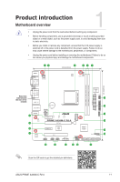
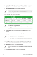
Chassis intrusion header (4-1 pin CHASSIS) This connector is for a chassis-mounted intrusion detection sensor or switch. Connect one end of the chassis intrusion sensor or switch cable to this connector. The chassis intrusion sensor or switch sends a high-level signal to this connector when a chassis component is removed or replaced. The signal is then generated as a chassis intrusion event. The chassis intrusion detection feature is disabled by default. To enable it, set the Chassis Intrude Detect Support item in the BIOS to [On]. Serial ATA 6.0Gb/s connectors (7-pin SATA6G_1~4) These connectors connect to Serial ATA 6.0 Gb/s hard disk drives via Serial ATA 6.0 Gb/s signal cables. System panel connector (10-1 pin F_PANEL) This connector supports several chassis-mounted functions. Speaker connector (4-pin SPEAKER) This 4-pin connector is for the chassis-mounted system warning speaker. The speaker allows you to hear system beeps and warnings. USB 3.0 connector (20-1 pin USB3_12) Connect a USB 3.0 module to this connector for additional USB 3.0 front or rear panel ports. This connector complies with USB 3.0 specifications and provides faster data transfer speeds of up to 5 Gbps, faster charging time for USBchargeable devices, optimized power efficiency, and backward compatibility with USB 2.0. USB 2.0 connectors (10-1 pin USB34, USB56) Connect the USB module cable to any of these connectors, then install the module to a slot opening at the back of the system chassis. These USB connectors comply with USB 2.0 specifications and support up to 480Mbps connection speed. Front panel audio connector (10-1 pin AAFP) This connector is for a chassis-mounted front panel audio I/O module that supports either HD Audio or legacy AC`97 audio standard. Connect one end of the front panel audio I/O module cable to this connector. • We recommend that you connect a high-definition front panel audio module to this connector to avail of the motherboard's high-definition audio capability. • If you want to connect a high-definition front panel audio module to this connector, set the Front Panel Type item in the BIOS setup to [HD Audio]. If you want to connect an AC'97 front panel audio module to this connector, set the item to [AC97]. By default, this connector is set to [HD Audio]. 1-4 Chapter 1: Product introduction
-
 1
1 -
2
-
3
-
4
-
5
-
6
-
 7
7 -
 8
8 -
 9
9 -
 10
10 -
 11
11 -
 12
12 -
 13
13 -
 14
14 -
 15
15 -
 16
16 -
 17
17 -
18
-
19
-
20
-
21
-
22
-
23
-
24
-
25
 |
 |