Asus PRIME H270M-PLUS/CSM User Guide - Page 14
System power LED 4-pin +PWR_LED
 |
View all Asus PRIME H270M-PLUS/CSM manuals
Add to My Manuals
Save this manual to your list of manuals |
Page 14 highlights
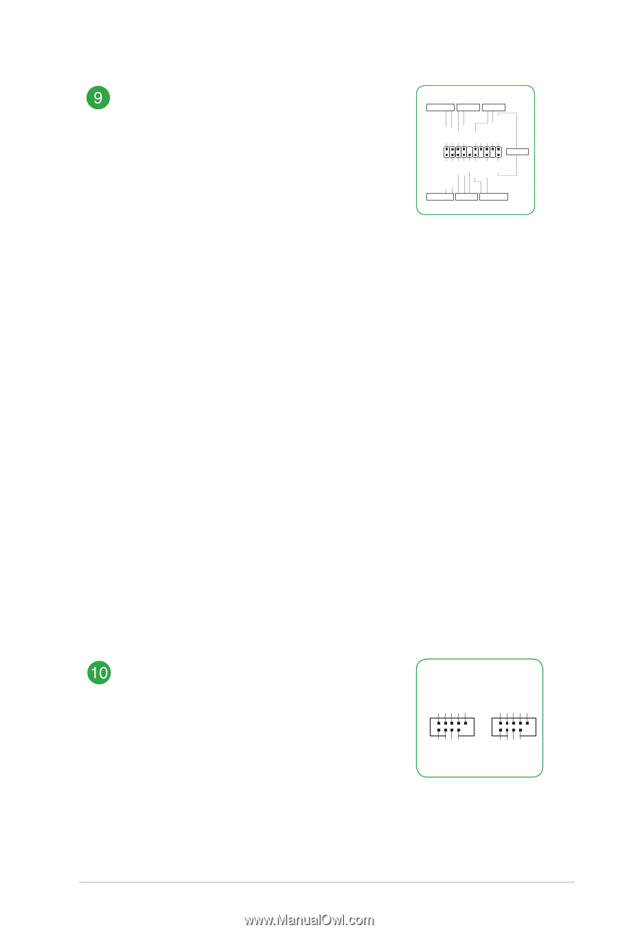
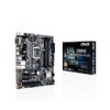
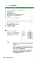
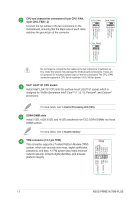
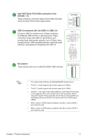
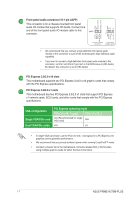
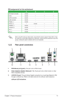
System panel connector (20-3 pin F_PANEL) This connector supports several chassis-mounted functions. PANEL +PWR_LED- PWR_SW SPEAKER PLED+ PLEDPWR Ground +5V Ground Ground Speaker CASEOPEN • System power LED (4-pin +PWR_LED-) PIN 1 CHASSIS HDD_LED+ HDD_LED- GND Reset +5V PLED+ PLED- GND This 2-pin connector is for the system power LED. Connect the chassis power LED cable to this connector. The system power LED lights up when you turn on the system power, and blinks when +HDD_LED- RESET +PWR_LED* Requires an ATX power supply the system is in sleep mode. • Hard disk drive activity LED (2-pin +HDD_LED-) This 2-pin connector is for the HDD Activity LED. Connect the HDD Activity LED cable to this connector. The HDD LED lights up or flashes when data is read from or written to the HDD. • System warning speaker (4-pin SPEAKER) This 4-pin connector is for the chassis-mounted system warning speaker. The speaker allows you to hear system beeps and warnings. • ATX power button/soft-off button (2-pin PWR_SW) This connector is for the system power button. Pressing the power button turns the system on or puts the system in sleep or soft-off mode depending on the operating system settings. Pressing the power switch for more than four seconds while the system is ON turns the system OFF. • Reset button (2-pin RESET) This 2-pin connector is for the chassis-mounted reset button for system reboot without turning off the system power. • Chassis intrusion header (2-pin CHASSIS) This connector is for a chassis-mounted intrusion detection sensor or switch. Connect one end of the chassis intrusion sensor or switch cable to this connector. The chassis intrusion sensor or switch sends a high-level signal to this connector when a chassis component is removed or replaced. The signal is then generated as a chassis intrusion event. USB+5V USB_P11USB_P11+ GND NC USB+5V USB_P13USB_P13+ GND NC USB 2.0 connectors (10-1 pin USB1112, USB1314) Connect a USB module cable to any of these connectors, then install the module to a slot opening at the back of the system chassis. These USB connectors comply with USB 2.0 specifications and supports up to 480Mbps connection speed. USB1112 USB1314 PIN 1 PIN 1 USB+5V USB_P12USB_P12+ GND USB+5V USB_P14USB_P14+ GND 1-5 ASUS PRIME H270M-PLUS
-
 1
1 -
2
-
3
-
4
-
5
-
6
-
7
-
8
-
 9
9 -
 10
10 -
 11
11 -
 12
12 -
 13
13 -
 14
14 -
 15
15 -
 16
16 -
 17
17 -
 18
18 -
 19
19 -
20
-
21
-
22
-
23
-
24
-
25
-
26
-
27
-
28
-
29
-
30
-
31
-
32
-
33
-
34
-
35
-
36
-
37
 |
 |