Asus PRIME H270M-PLUS/CSM User Guide - Page 15
Serial port connector 10-1 pin COM, Clear RTC RAM 2-pin CLRTC, To erase the RTC RAM, Digital audio
 |
View all Asus PRIME H270M-PLUS/CSM manuals
Add to My Manuals
Save this manual to your list of manuals |
Page 15 highlights
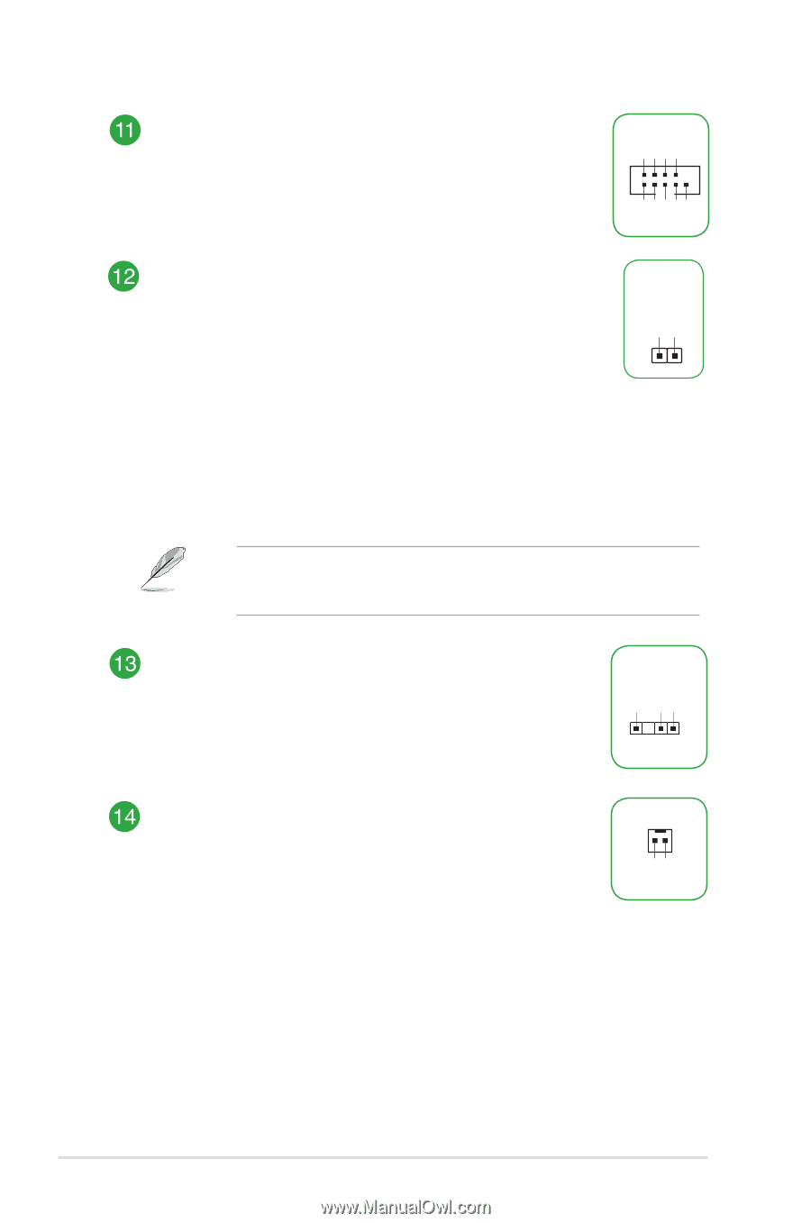
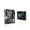
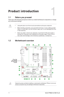
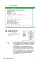
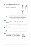
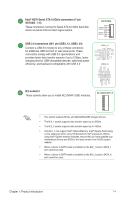
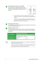
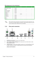
RXD DTR DSR CTS Serial port connector (10-1 pin COM) This connector is for a serial (COM) port. Connect the serial port module cable to this connector, then install the module to a slot opening at the back of the system chassis. COM PIN 1 DCD TXD GND RTS RI Clear RTC RAM (2-pin CLRTC) This header allows you to clear the CMOS RTC RAM data of the system setup information such as date, time, and system passwords. To erase the RTC RAM: 1. Turn OFF the computer and unplug the power cord. 2. Use a metal object such as a screwdriver to short the two pins. 3. Plug the power cord and turn ON the computer. 4. Hold down the key during the boot process and enter BIOS setup to re-enter data. +3V_BAT GND CLRTC PIN 1 If the steps above do not help, remove the onboard battery and short the two pins again to clear the CMOS RTC RAM data. After clearing the CMOS, reinstall the battery. Digital audio connector (4-1 pin SPDIF_OUT) This connector is for an additional Sony/Philips Digital Interface (S/PDIF) port. Connect the S/PDIF Out module cable to this connector, then install the module to a slot opening at the back of the system chassis. +5V SPDIFOUT GND SPDIF_OUT Mono out header (2-pin MONO_OUT) This internal mono out header allows connection to an internal, low power speaker for basic system sound capability. The subsystem is capable of driving a speaker load of 4 Ohms at 2 Watts (rms). MONO_OUT PIN 1 R_OUTR_OUT+ Chapter 1: Product introduction 1-6
-
 1
1 -
2
-
3
-
4
-
5
-
6
-
7
-
8
-
9
-
 10
10 -
 11
11 -
 12
12 -
 13
13 -
 14
14 -
 15
15 -
 16
16 -
 17
17 -
 18
18 -
 19
19 -
 20
20 -
21
-
22
-
23
-
24
-
25
-
26
-
27
-
28
-
29
-
30
-
31
-
32
-
33
-
34
-
35
-
36
-
37
 |
 |