Asus PRIME H610M-E Users Manual English - Page 12
Motherboard layout, Layout contents
 |
View all Asus PRIME H610M-E manuals
Add to My Manuals
Save this manual to your list of manuals |
Page 12 highlights
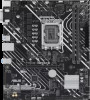
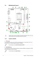
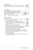
1.2 Motherboard layout 5 6 1 10 4 2 10 21.1cm(8.3in) KBMS HDMI VGA DP ATX_12V ADD_GEN 2_3 CPU_FAN DIGI+ VRM ADD_GEN 2_2 4 CHA_FAN2 ATX_PWR DDR5 DIMM_A (64bit, 288-pin module) DDR5 DIMM_B (64bit, 288-pin module) 24.4cm(9.6in) U32G1_12 5 LGA1700 LAN_USB_914 U32G1_34 CHA_FAN1 PCIE SATA 3.0 X4 X 4 M.2_1(SOCKET3) 8 AUDIO 2280 2260 2242 PCIEX16(G4) 3 Ethernet BATTERY 6 Super I/O Intel® H610 M.2_2(SOCKET3) PCIE SATA 3.0 X2 X SATA6G_3 2280 2260 2242 TPM Audio Codec PCIEX1(G3) 17 3 AAFP COM SPDIF_OUT COM_DEBUG CLRTC ADD_GEN 2_1 USB_56 USB_7 SATA6G_1 SATA6G_2 128Mb BIOS SPEAKER SATA6G_4 16 RGB_HEADER F_PANEL 14 13 15 11 12 10 9 7 18 Unplug the power cord before installing or removing the motherboard. Failure to do so can cause you physical injury and damage motherboard components. 1.2.1 Layout contents 1. CPU socket The motherboard comes with a LGA1700 socket designed for 13th Gen Intel® Core™ & 12th Gen Intel® Core™, Pentium® Gold and Celeron® Processors. For more details, refer to Central Processing Unit (CPU). 2. DDR5 DIMM slots The motherboard comes with Dual Inline Memory Modules (DIMM) slots designed for DDR5 (Double Data Rate 5) memory modules. For more details, refer to System memory. 1-2 Chapter 1: Product Introduction
-
 1
1 -
2
-
3
-
4
-
5
-
6
-
 7
7 -
 8
8 -
 9
9 -
 10
10 -
 11
11 -
 12
12 -
 13
13 -
 14
14 -
 15
15 -
 16
16 -
 17
17 -
18
-
19
-
20
-
21
-
22
-
23
-
24
-
25
-
26
-
27
-
28
-
29
-
30
-
31
-
32
-
33
 |
 |
