Asus PRL-DL PRL-DL M/B User Guide - Page 28
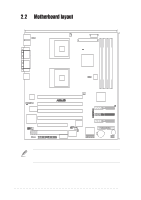
Motherboard layout
 |
View all Asus PRL-DL manuals
Add to My Manuals
Save this manual to your list of manuals |
Page 28 highlights
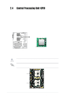
DDR DIMM1 (64/72 bit, 184-pin module) DDR DIMM2 (64/72 bit, 184-pin module) DDR DIMM3 (64/72 bit, 184-pin module) DDR DIMM4 (64/72 bit, 184-pin module) 30.7cm (12.08in) 2.2 Motherboard layout PS/2 T: Mouse B: Keyboard J1 USB0 USB1 COM1 PARALLEL PORT VGA RJ-45 mPGA604 26.67.cm (10.4in) FAN2 CON12V ATX_POWER CPULED1 ServerWorks® GCSL North Bridge JFSB1 SW1 mPGA604 01 23 45 67 Intel 82540 Gigabit Ethernet JLAN1 JVGA1 STBYLED1 PCI64-1 (64-bit, 33MHz 3V) ® PRL-DL PCI64-2 (64-bit, 33MHz 3V) FAN1 ServerWorks ® CSB6 South Bridge IDE2 POWERLED1 VGA RAM PCI64-3 (64-bit, 33MHz 3V) ATI RAGE XL PCI64-4 (64-bit, 33MHz 3V) VGA Controller 4Mbit Flash PCI1 (32-bit, 33MHz 5V) BIOS LED1 LED2 LED3 LED4 LED5 LED6 LED7 LED8 IDE1 IDE3 CON1 COM2 PCI2 (32-bit, 33MHz 5V) CON2 SW2 J1 J3 Super I/O FAN3 ASUS ASIC CLRCMOS1 with Hardware Monitor ASUS PANEL1 CR2032 3V Lithium Cell CMOS Power FLOPPY1 BUZZ1 USB2.3 The PCI2 32-bit, 4-pin CON1 and 80-pin ASMB connector features are optional. These components are grayed out in the above motherboard layout. 2-2 Chapter 2: Hardware information
-
 1
1 -
2
-
3
-
4
-
5
-
6
-
7
-
8
-
9
-
10
-
11
-
12
-
13
-
14
-
15
-
16
-
17
-
18
-
19
-
20
-
21
-
22
-
 23
23 -
 24
24 -
 25
25 -
 26
26 -
 27
27 -
 28
28 -
 29
29 -
 30
30 -
 31
31 -
 32
32 -
 33
33 -
34
-
35
-
36
-
37
-
38
-
39
-
40
-
41
-
42
-
43
-
44
-
45
-
46
-
47
-
48
-
49
-
50
-
51
-
52
-
53
-
54
-
55
-
56
-
57
-
58
-
59
-
60
-
61
-
62
-
63
-
64
-
65
-
66
-
67
-
68
-
69
-
70
-
71
-
72
-
73
-
74
-
75
-
76
-
77
-
78
-
79
-
80
-
81
-
82
-
83
-
84
-
85
-
86
-
87
-
88
-
89
-
90
-
91
-
92
-
93
-
94
-
95
-
96
-
97
-
98
-
99
-
100
-
101
-
102
-
103
-
104
-
105
-
106
-
107
-
108
-
109
-
110
-
111
-
112
-
113
-
114
 |
 |
