Asus PU-DL Manual pdf format file for PU-DLS/PU-DL M/B - Page 11
PU-DLS/PU-DL specifications summary - pu dls chipset
 |
View all Asus PU-DL manuals
Add to My Manuals
Save this manual to your list of manuals |
Page 11 highlights
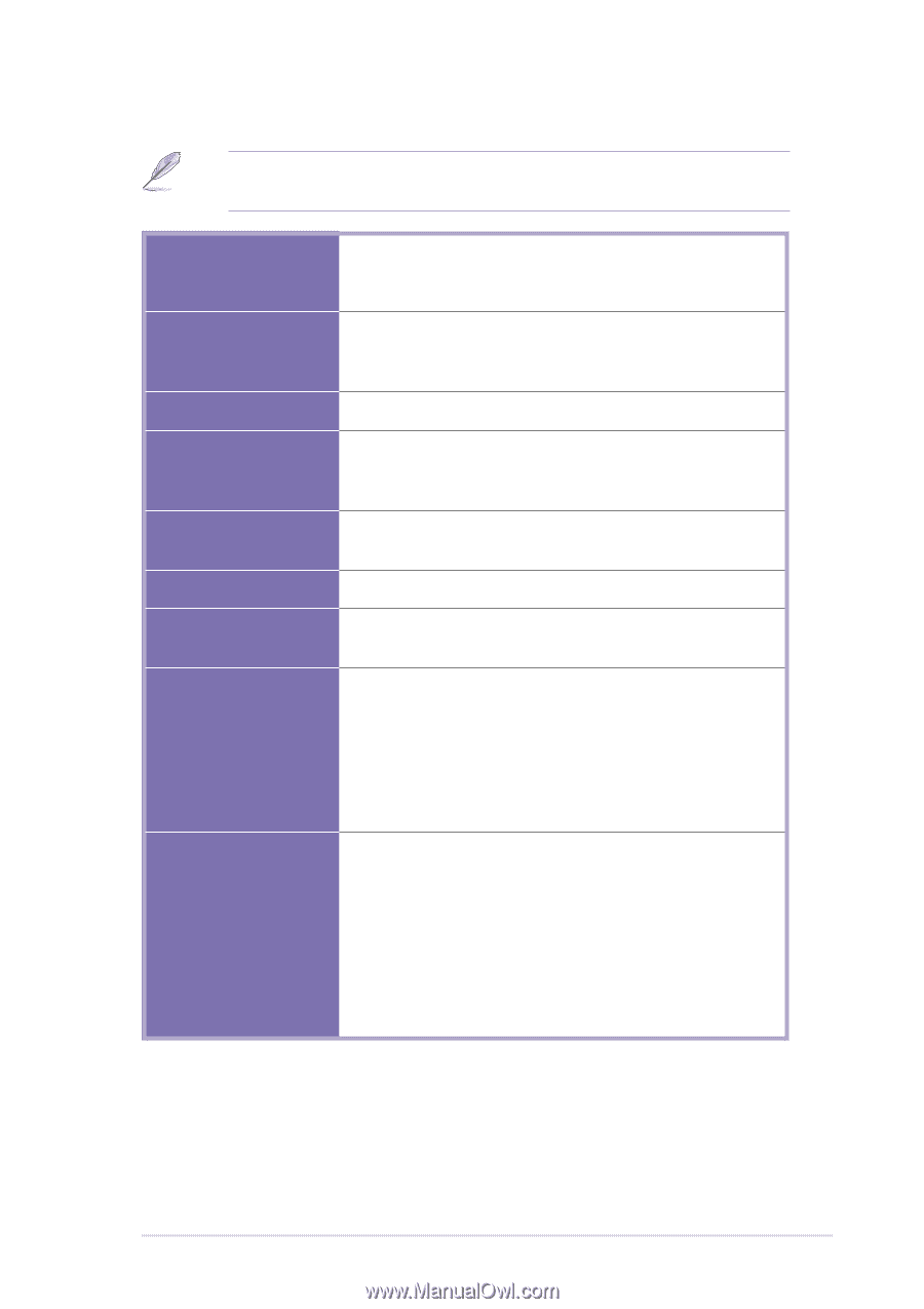
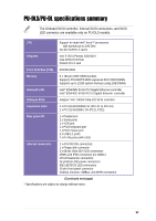
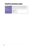
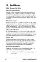
PU-DLS/PU-DL specifications summary The Onboard SCSI controller, internal SCSI connectors, and SCSI LED connector are available only on PU-DLS models. CPU Support for dual Intel® Xeon™ processors with speeds up to 3.06 GHz On-die 512KB L2 cache Chipsets Intel E7501 (Plumas 533) MCH Intel ICH3-S I/O Hub P64H2 PCI-X Hub Front Side Bus (FSB) 533/400 MHz Memory 6 x 184-pin DDR DIMM sockets Supports PC2100/PC1600 registered ECC DDR DIMMs Supports up to 12GB system memory using 2GB DIMMs Onboard LAN Intel® 82540EM 32-bit PCI Gigabit Ethernet controller Intel® 82544GC 64-bit PCI-X Gigabit Ethernet controller Onboard SCSI Adaptec® AIC-7902W Ultra-320 SCSI controller Expansion slots 4 x PCI 64-bit/100MHz 3V (PCI-X1 to PCI-X4) 2 x PCI 32-bit/33MHz 5V (PCI1, PCI2) Rear panel I/O 1 x Parallel port 2 x Serial ports 1 x VGA port 1 x PS/2 keyboard port 1 x PS/2 mouse port 2 x USB 1.1 ports 2 x RJ-45 ports (with LED) Internal connectors 2 x ATA/100 IDE connectors 1 x Floppy disk connector 2 x 68-pin Ultra 320 SCSI connectors eRMC and IPMI connectors (for ASMC) CPU/Chassis fan connectors 24-pin/8-pin SSI power connectors IDE LED/SCSI LED connectors 20-pin Front panel connector Chassis intrusion, SMBus, and WOR connectors (Continued next page) * Specifications are subject to change without notice. xi
-
 1
1 -
2
-
3
-
4
-
5
-
 6
6 -
 7
7 -
 8
8 -
 9
9 -
 10
10 -
 11
11 -
 12
12 -
 13
13 -
 14
14 -
 15
15 -
 16
16 -
17
-
18
-
19
-
20
-
21
-
22
-
23
-
24
-
25
-
26
-
27
-
28
-
29
-
30
-
31
-
32
-
33
-
34
-
35
-
36
-
37
-
38
-
39
-
40
-
41
-
42
-
43
-
44
-
45
-
46
-
47
-
48
-
49
-
50
-
51
-
52
-
53
-
54
-
55
-
56
-
57
-
58
-
59
-
60
-
61
-
62
-
63
-
64
-
65
-
66
-
67
-
68
-
69
-
70
-
71
-
72
-
73
-
74
-
75
-
76
-
77
-
78
-
79
-
80
-
81
-
82
-
83
-
84
-
85
-
86
-
87
-
88
-
89
-
90
-
91
-
92
-
93
-
94
-
95
-
96
-
97
-
98
-
99
-
100
-
101
-
102
-
103
-
104
-
105
-
106
-
107
-
108
-
109
-
110
-
111
-
112
-
113
-
114
-
115
-
116
-
117
-
118
-
119
-
120
-
121
-
122
-
123
-
124
-
125
-
126
-
127
-
128
-
129
-
130
-
131
-
132
-
133
-
134
 |
 |