Asus Pro H610T D4-CSM PRO H610T D4 Users Manual English - Page 10
Layout contents, CPU socket, DDR4 SO-DIMM slots, Fan headers, Power connectors, M.2 slot Key M
 |
View all Asus Pro H610T D4-CSM manuals
Add to My Manuals
Save this manual to your list of manuals |
Page 10 highlights
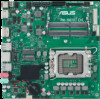
1.2.1 Layout contents 1. CPU socket The motherboard comes with a surface mount Intel® Socket LGA1700 designed for 12th Gen Intel® Core™, Pentium® Gold and Celeron® Processors. For more details, refer to Central Processing Unit (CPU). 2. DDR4 SO-DIMM slots This motherboard comes with two Double Data Rate 4 (DDR4) Small Outline Dual Inline Memory Modules (SO-DIMM) slots. For more details, refer to System memory. 3. Fan headers The Fan headers allow you to connect fans to cool the system. FAN PWM FAN IN FAN PWR GND 4. Power connectors These Power connectors allow you to connect your motherboard to a power supply. The power supply plugs are designed to fit in only one orientation. Find the proper orientation and push down firmly until the power supply plugs are fully inserted. These power connectors support 19V. Refer to the specification sheet for more details. 5. M.2 slot (Key M) The M.2 slot allows you to install an M.2 device such as an M.2 SSD module. Intel® 12th Gen Processors - M.2 slot (Key M), type 2260/2280 (supports PCIe 4.0 x4 & SATA modes). 6. SATA 6Gb/s ports The SATA 6Gb/s ports allow you to connect SATA devices such as optical disc drives and hard disk drives via SATA cables. 7. USB 3.2 Gen 1 header The USB 3.2 Gen 1 header allows you to connect a USB 3.2 Gen 1 module for additional USB 3.2 Gen 1 ports. The USB 3.2 Gen 1 header provides data transfer speeds of up to 5 Gb/s. USB3+5V IntA_P4_SSRXIntA_P4_SSRX+ GND IntA_P4_SSTXIntA_P4_SSTX+ GND IntA_P4_DIntA_P4_D+ PIN 1 USB3+5V IntA_P3_SSRXIntA_P3_SSRX+ GND IntA_P3_SSTXIntA_P3_SSTX+ GND IntA_P3_DIntA_P3_D+ GND The USB 3.2 Gen 1 module is purchased separately. 8. USB 2.0 headers The USB 2.0 headers allow you to connect a USB module for additional USB 2.0 ports. The USB 2.0 headers provide data transfer speeds of up to 480 Mb/s. USBE3 Groud Data(positive) Data(negative) +5V DC PIN 1 NC GND USB_P7+ USB_P7USB+5V GND USB_P8+ USB_P8USB+5V PIN 1 1-2 Chapter 1: Product Introduction
-
 1
1 -
2
-
3
-
4
-
 5
5 -
 6
6 -
 7
7 -
 8
8 -
 9
9 -
 10
10 -
 11
11 -
 12
12 -
 13
13 -
 14
14 -
 15
15 -
16
-
17
-
18
-
19
-
20
-
21
-
22
-
23
-
24
-
25
-
26
-
27
-
28
-
29
-
30
 |
 |
