Asus Pro H610T D4-CSM PRO H610T D4 Users Manual English - Page 12
COM Debug header, DMIC header, Front Panel Audio header, FPD Brightness header, LVDS header
 |
View all Asus Pro H610T D4-CSM manuals
Add to My Manuals
Save this manual to your list of manuals |
Page 12 highlights
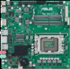
GND GND O_COM1_TXD1 14. COM Debug header This header allows connection to a COM Debug card. The COM Debug Card is purchased separately. COM_DEBUG PIN 1 O_COMDBG_P80 +3V 15. DMIC header The DMIC header is for connecting the digital microphone module used in All-in-One chassis. DMIC PIN 1 +3V DMIC_DATA GND DMIC_CLK AGND NC SENSE1_RETUR SENSE2_RETUR 16. Front Panel Audio header This header is for a chassis-mounted front panel audio I/O module that supports HD audio standard. Connect one end of the front panel audio I/O module cable to this header. • We recommend that you connect a high-definition front panel audio module to this header to avail of the motherboard's high- AAFP definition audio capability. PORT1 L PORT1 R PORT2 R SENSE_SEND PORT2 L • If you want to connect a high-definition front panel audio module to this header, set the Front Panel Type item in the BIOS setup to [HD Audio]. By default, this header is set to [HD Audio]. HD-audio-compliant pin definition 17. FPD Brightness header This header is for the LCD panel backlight and brightness controls. It enables the LCD panel backlight, provides backlight control signals, and provides brightness control signals for the brightness button on the front panel. LCD_BLKT_PANEL PIN 1 INV_ENABKL_S LCD_BL_PWM_R BLKT_PWR BLKT_PWR GND GND H_LCD_BRI_UP H_LCD_BRI_DOWN 18. LVDS header This header is for an LCD monitor that supports Low Voltage Differential Signalling (LVDS) interface. 19. M.2 slot (Key E) This slot allows you to install an M.2 (WIFI) module. LVDS_DDC_DAT N/C BLKT_PWR BLKT_PWR BLKT_PWR LVDS_TX_TCLK1N LVDS_TX_TCLK1P LCD_BL_PWM_R INV_ENABKL_S LVDS_DDC_SCL GND GND GND LVDS_TX_TCLK0N LVDS_TX_TCLK0P GND GND GND +3V N/C LCD_VCC LCD_VCC LCD_VCC GND LVDS_TX_TA1N_R LVDS_TX_TA1P_R LVDS_TX_TB1N_R LVDS_TX_TB1P_R LVDS_TX_TC1N_R LVDS_TX_TC1P_R LVDS_TX_TD1N_R LVDS_TX_TD1P_R LVDS_TX_TA0N_R LVDS_TX_TA0P_R LVDS_TX_TB0N_R LVDS_TX_TB0P_R LVDS_TX_TC0N_R LVDS_TX_TC0P_R LVDS_TX_TD0N_R LVDS_TX_TD0P_R LVDS PIN 40 PIN 1 20. Panel Off header This 2-pin header is for connecting a monitor switch that can turn off the LCD panel display backlight. PANEL_SW GND MONITER_SW PIN 1 1-4 Chapter 1: Product Introduction
-
 1
1 -
2
-
3
-
4
-
5
-
6
-
 7
7 -
 8
8 -
 9
9 -
 10
10 -
 11
11 -
 12
12 -
 13
13 -
 14
14 -
 15
15 -
 16
16 -
 17
17 -
18
-
19
-
20
-
21
-
22
-
23
-
24
-
25
-
26
-
27
-
28
-
29
-
30
 |
 |
