Asus Q170T/CSM User Guide - Page 12
Embedded DisplayPort 40-pin EDP
 |
View all Asus Q170T/CSM manuals
Add to My Manuals
Save this manual to your list of manuals |
Page 12 highlights
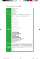
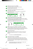
System panel connector (10-1 pin PANEL) This connector supports several chassis-mounted functions. Embedded DisplayPort (40-pin EDP) This connector is for an internal embedded DisplayPort connection. LVDS connector (40-pin LVDS) This connector is for an LCD monitor that supports Low-voltage Differential Signaling (LVDS) interface. LVDS panel/eDP selector (3-pin FPD_SEL) FPD_SEL Pins 1-2 (Default) 2-3 Setting LVDS eDP for LVDS (Default) for eDP LCD panel backlight header (8-pin LCD_BLKT_PANEL) This connector is for the LCD panel backlight and brightness controls. It enables the LCD panel backlight, provides backlight control signals, and provides brightness control signals for the brightness button on the front panel. Backlight inverter voltage selection header (3-pin BLKT_PWR_SEL) 12 23 12 23 BLKT_PWR_SEL 12V 19V (Default) Pins 1-2 (Default) 2-3 Setting 12V 19V USB 2.0 connectors (10-1 pin USB78, 10-2 pin USB910; 5-1 pin USB11) Connect the USB module cable to these connectors, then install the module to a slot opening at the back of the system chassis. These USB connectors comply with USB 2.0 specifications and support up to 480Mbps connection speed. Intel® LGA1151 CPU socket Install Intel® LGA1151 CPU into this surface mount LGA1151 socket, which is designed for 6th Generation Intel® Core™ i7 / i5 / i3, Pentium®, and Celeron® processors For more details, refer to Central Processing Unit (CPU). Chassis intrusion header (4-1 pin CHASSIS) This connector is for a chassis-mounted intrusion detection sensor or switch. Connect one end of the chassis intrusion sensor or switch cable to this connector. The chassis intrusion sensor or switch sends a high-level signal to this connector when a chassis component is removed or replaced. The signal is then generated as a chassis intrusion event. The chassis intrusion detection feature is disabled by default. To enable it, set the Chassis Intrude Detect Support item in the BIOS to [On]. 1-3 ASUS Q170T E11582_Q170T_UM.indb 3 2016-05-05 10:16:51
-
 1
1 -
2
-
3
-
4
-
5
-
6
-
 7
7 -
 8
8 -
 9
9 -
 10
10 -
 11
11 -
 12
12 -
 13
13 -
 14
14 -
 15
15 -
 16
16 -
 17
17 -
18
-
19
-
20
-
21
-
22
-
23
-
24
-
25
-
26
-
27
-
28
 |
 |
