Asus Q170T/CSM User Guide - Page 13
Clrtc
 |
View all Asus Q170T/CSM manuals
Add to My Manuals
Save this manual to your list of manuals |
Page 13 highlights
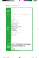
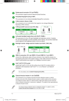
M.2 socket 3 This socket allows you to install an M.2 (NGFF) SSD module. Use the bundled screw 13020-0181000 to secure your M.2 device. This socket supports M Key and 2242/2260/2280 storage devices. Clear RTC RAM (2-pin CLRTC) This header allows you to clear the CMOS RTC RAM data of the system setup information such as date, time, and system passwords. To erase the RTC RAM: 1. Turn OFF the computer and unplug the power cord. 2. Use a metal object such as a screwdriver to short the two pins. 3. Plug the power cord and turn ON the computer. 4. Hold down the key during the boot process and enter BIOS setup to re-enter data. +3V_BAT GND CLRTC PIN 1 If the steps above do not help, remove the onboard battery and short the two pins again to clear the CMOS RTC RAM data. After clearing the CMOS, reinstall the battery. Intel® ME jumper (3-pin DIS_ME) This jumper allows you to enable or disable the Intel® ME function. Set this jumper to pins 1-2 to enable (default) the Intel® ME function and to pins 2-3 to disable it. Disable the Intel® ME function before updating it. Front panel audio connector (10-1 pin AAFP) This connector is for a chassis-mounted front panel audio I/O module that supports HD Audio. Connect one end of the front panel audio I/O module cable to this connector. We recommend that you connect a high-definition front panel audio module to this connector to avail of the motherboard's high-definition audio capability DMIC connector (5-1 pin DMIC) The DMIC connector is for connecting the digital microphone module used in Allin-One chassis. 24 Internal stereo speaker header (4-pin SPK_OUT) The internal mono speaker header allows connection to an internal, low-power speaker for basic system sound capability. The subsystem is capable of driving a speaker load of 4 Ohms at 3 Watts (rms). Chapter 1: Product introduction E11582_Q170T_UM.indb 4 1-4 2016-05-05 10:16:51
-
 1
1 -
2
-
3
-
4
-
5
-
6
-
7
-
 8
8 -
 9
9 -
 10
10 -
 11
11 -
 12
12 -
 13
13 -
 14
14 -
 15
15 -
 16
16 -
 17
17 -
 18
18 -
19
-
20
-
21
-
22
-
23
-
24
-
25
-
26
-
27
-
28
 |
 |
