Asus T5-P5G41E User Manual - Page 14
Internal components, Serial ATA connectors - motherboard
 |
View all Asus T5-P5G41E manuals
Add to My Manuals
Save this manual to your list of manuals |
Page 14 highlights
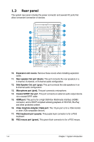
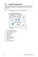
1.4 Internal components The illustration below is the internal view of the system when you remove the top cover and the power supply unit. The installed components are labeled for your reference. The illustration shows an open chassis lifted at a 90o angle. 1 2 5 4 6 7 8 9 3 1. 5.25-inch optical drive cage 2. 3.5-inch hard disk drive cage 3. Power supply unit 4. DIMM sockets 5. CPU socket 6. ASUS motherboard 7. PCI Express x16 slot 8. PCI slot 9. Serial ATA connectors 1-6 Chapter 1: System introduction
-
 1
1 -
2
-
3
-
4
-
5
-
6
-
7
-
8
-
 9
9 -
 10
10 -
 11
11 -
 12
12 -
 13
13 -
 14
14 -
 15
15 -
 16
16 -
 17
17 -
 18
18 -
 19
19 -
20
-
21
-
22
-
23
-
24
-
25
-
26
-
27
-
28
-
29
-
30
-
31
-
32
-
33
-
34
-
35
-
36
-
37
-
38
-
39
-
40
-
41
-
42
-
43
-
44
-
45
-
46
-
47
-
48
-
49
-
50
-
51
-
52
-
53
-
54
-
55
-
56
-
57
-
58
-
59
-
60
-
61
-
62
-
63
-
64
-
65
-
66
-
67
-
68
-
69
-
70
-
71
-
72
-
73
-
74
-
75
-
76
 |
 |

1-6
Chapter 1: System introduction
1.4
Internal components
The illustration below is the internal view of the system when you remove the top
cover and the power supply unit. The installed components are labeled for your
reference.
The illustration shows an open chassis lifted at a 90
o
angle.
1
2
3
4
5
6
7
8
1.
5.25-inch optical drive cage
2.
3.5-inch hard disk drive cage
3.
Power supply unit
4.
DIMM sockets
5.
CPU socket
6.
ASUS motherboard
7.
PCI Express x16 slot
8.
PCI slot
9.
Serial ATA connectors
9