Asus TUA266 TUA266 User Manual - Page 16
ASUS TUA266 User's Manual
 |
View all Asus TUA266 manuals
Add to My Manuals
Save this manual to your list of manuals |
Page 16 highlights
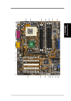
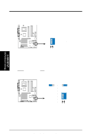
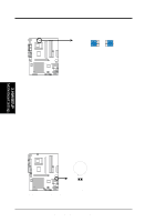
3. HARDWARE SETUP 14) CD/AUX/MODEM 15) MIC2 16) JTPWR 17) PWR.LED (PANEL) 18) SPEAKER (PANEL) 19) MSG.LED (PANEL) 20) SMI (PANEL) 21) PWR.SW (PANEL) 22) RESET (PANEL) p. 39 Internal Audio Connectors (4-1 pin) p. 39 Internal Microphone Connector (3-pin) p. 40 Power Supply Thermal Sensor (2-pin) p. 41 System Power LED Lead (3-pin) p. 41 System Warning Speaker Lead (4-pin) p. 41 System Message LED Lead (2-pin) p. 41 System Management Interrupt Lead (2-pin) p. 41 ATX / Soft-Off Switch Lead (2-pin) p. 41 Reset Switch Lead (2-pin) 3. H/W SETUP Layout Contents 16 ASUS TUA266 User's Manual
-
 1
1 -
2
-
3
-
4
-
5
-
6
-
7
-
8
-
9
-
10
-
 11
11 -
 12
12 -
 13
13 -
 14
14 -
 15
15 -
 16
16 -
 17
17 -
 18
18 -
 19
19 -
 20
20 -
 21
21 -
22
-
23
-
24
-
25
-
26
-
27
-
28
-
29
-
30
-
31
-
32
-
33
-
34
-
35
-
36
-
37
-
38
-
39
-
40
-
41
-
42
-
43
-
44
-
45
-
46
-
47
-
48
-
49
-
50
-
51
-
52
-
53
-
54
-
55
-
56
-
57
-
58
-
59
-
60
-
61
-
62
-
63
-
64
-
65
-
66
-
67
-
68
-
69
-
70
-
71
-
72
-
73
-
74
-
75
-
76
-
77
-
78
-
79
-
80
-
81
-
82
-
83
-
84
-
85
-
86
-
87
-
88
-
89
-
90
-
91
-
92
-
93
-
94
 |
 |

16
ASUS TUA266 User’s Manual
3. HARDWARE SETUP
Layout Contents
3. H/W SETUP
14)
CD/AUX/MODEM
p. 39
Internal Audio Connectors (4-1 pin)
15)
MIC2
p. 39
Internal Microphone Connector (3-pin)
16)
JTPWR
p. 40
Power Supply Thermal Sensor (2-pin)
17)
PWR.LED (
PANEL
)
p. 41
System Power LED Lead (3-pin)
18)
SPEAKER (PANEL)
p. 41
System Warning Speaker Lead (4-pin)
19)
MSG.LED (PANEL)
p. 41
System Message LED Lead (2-pin)
20)
SMI (PANEL)
p. 41
System Management Interrupt Lead (2-pin)
21)
PWR.SW (PANEL)
p. 41
ATX / Soft-Off Switch Lead (2-pin)
22)
RESET (PANEL)
p. 41
Reset Switch Lead (2-pin)