Asus TUA266 TUA266 User Manual - Page 22
Memory Installation
 |
View all Asus TUA266 manuals
Add to My Manuals
Save this manual to your list of manuals |
Page 22 highlights
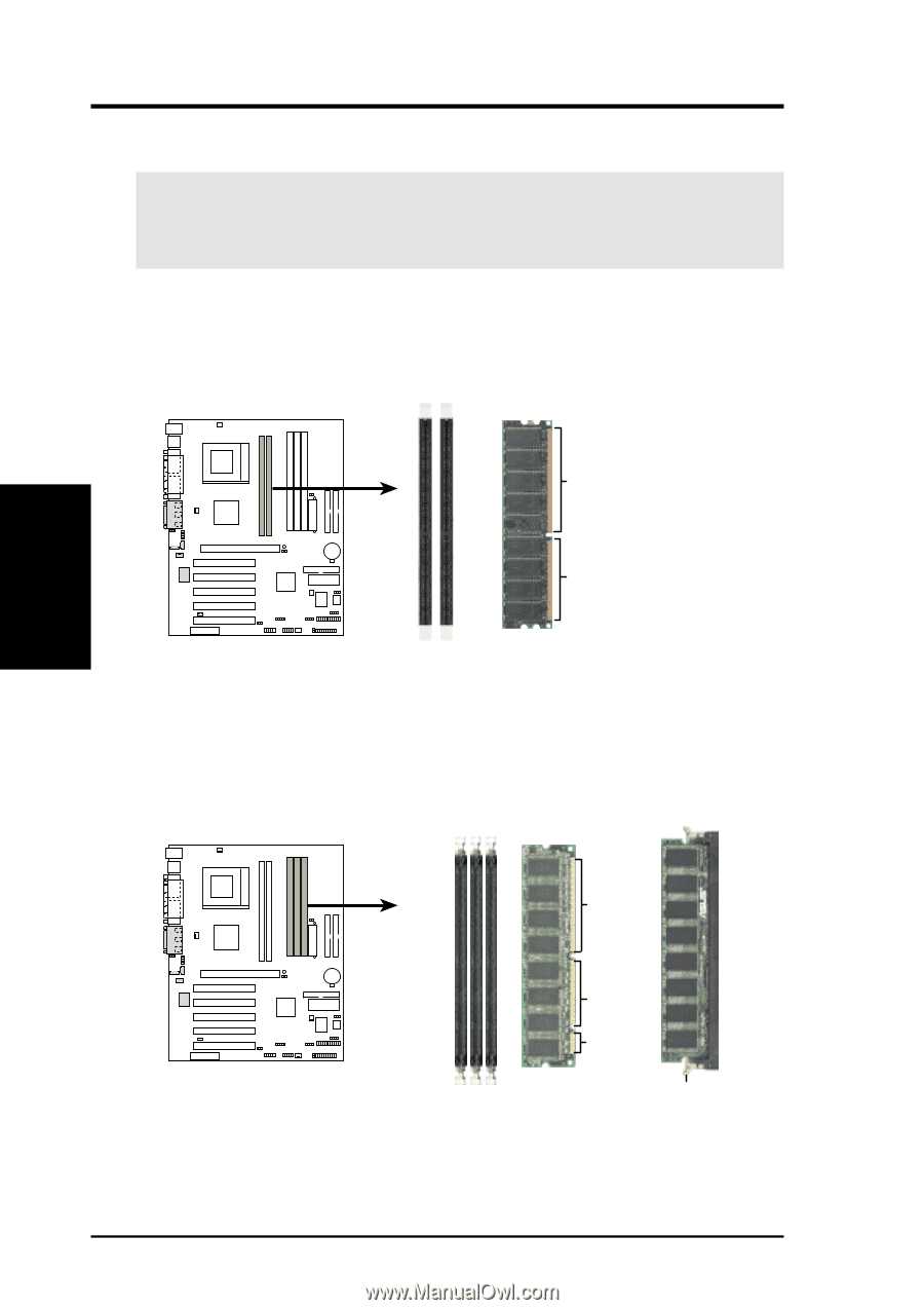
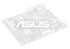
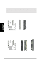
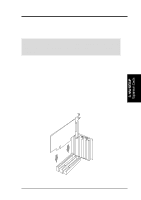
3. H/W SETUP System Memory 3. HARDWARE SETUP 3.5.2 Memory Installation WARNING! Make sure that you unplug the power supply when adding or removing memory modules or other system components. Failure to do so may cause severe damage to both the motherboard and the components. A 184-pin DDR SDRAM DIMM has a single notch near the center. The number of pins are different on either side of the notch so the module only fits in one direction. Insert a DDR DIMM into the DDR socket as shown. 01 01 01 01 104 Pins TUA266 80 Pins TUA266 184-Pin DDR DIMM Sockets A 168-pin SDR SDRAM DIMM has two notches. This feature differentiates an SDR DIMM from a DDR DIMM. The SDR DIMM notches match the breaks on the DIMM socket so the module only fits in one direction. Insert an SDR DIMM into the SDR socket as shown. TUA266 TUA266 168-Pin DIMM Sockets 88 Pins 60 Pins 20 Pins Lock 22 ASUS TUA266 User's Manual
-
 1
1 -
2
-
3
-
4
-
5
-
6
-
7
-
8
-
9
-
10
-
11
-
12
-
13
-
14
-
15
-
16
-
 17
17 -
 18
18 -
 19
19 -
 20
20 -
 21
21 -
 22
22 -
 23
23 -
 24
24 -
 25
25 -
 26
26 -
 27
27 -
28
-
29
-
30
-
31
-
32
-
33
-
34
-
35
-
36
-
37
-
38
-
39
-
40
-
41
-
42
-
43
-
44
-
45
-
46
-
47
-
48
-
49
-
50
-
51
-
52
-
53
-
54
-
55
-
56
-
57
-
58
-
59
-
60
-
61
-
62
-
63
-
64
-
65
-
66
-
67
-
68
-
69
-
70
-
71
-
72
-
73
-
74
-
75
-
76
-
77
-
78
-
79
-
80
-
81
-
82
-
83
-
84
-
85
-
86
-
87
-
88
-
89
-
90
-
91
-
92
-
93
-
94
 |
 |