Asus TUF B350M-PLUS GAMING User Guide - Page 13
USB 2.0 connectors 10-1 pin USB3~6, USB 3.1 Gen 1 connector 20-1 pin U31G1_12
 |
View all Asus TUF B350M-PLUS GAMING manuals
Add to My Manuals
Save this manual to your list of manuals |
Page 13 highlights
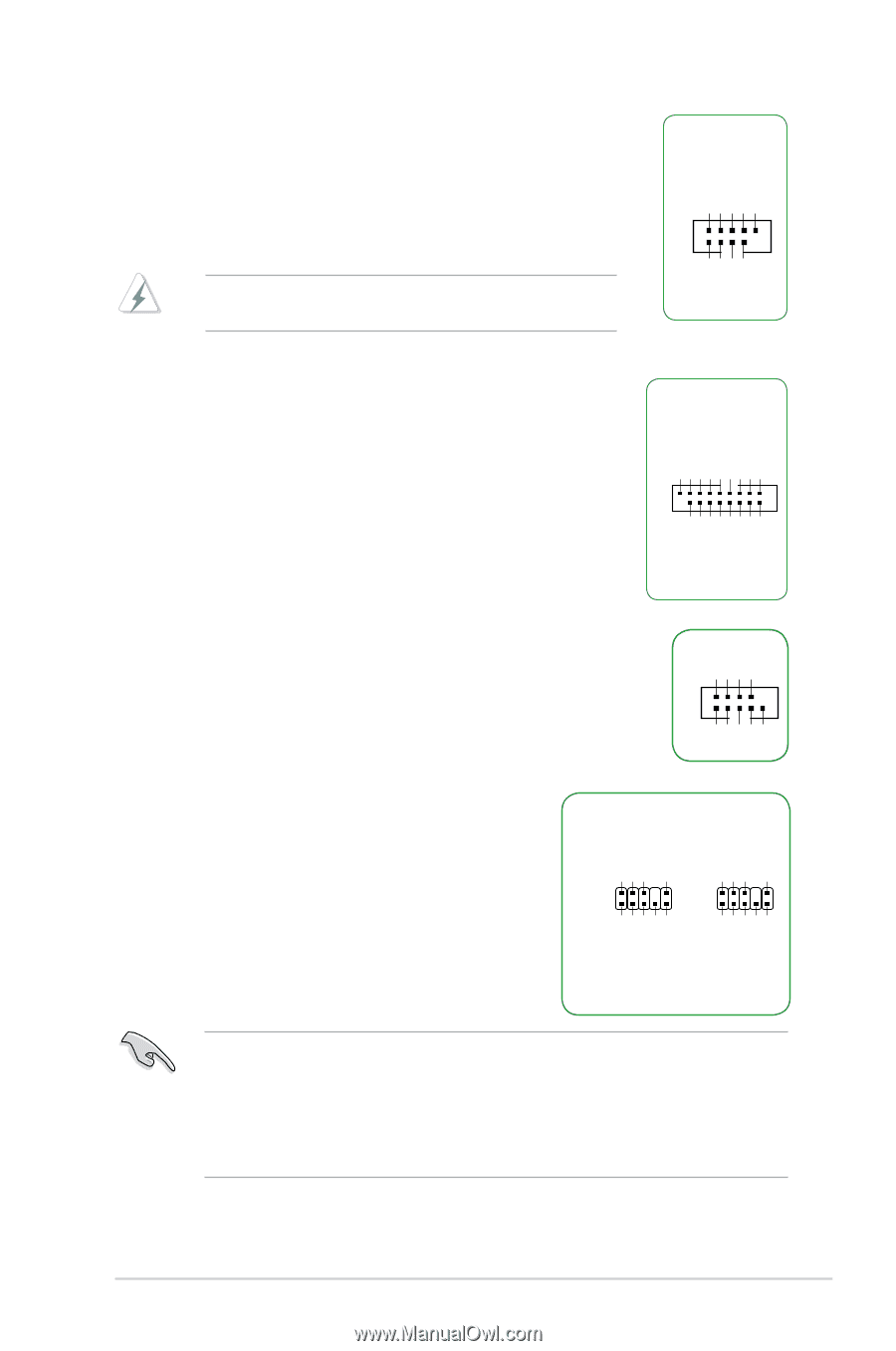
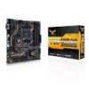
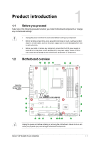
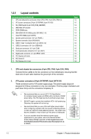
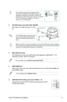
USB+5V USB_P3USB_P3+ GND NC 10. USB 2.0 connectors (10-1 pin USB3~6) These connectors are for USB 2.0 ports. Connect the USB module cable to any of these connector, then install the module to a slot opening at the back of the system chassis. These USB connectors comply with USB 2.0 specifications and supports up to 480Mbps connection speed. Never connect a 1394 cable to the USB connectors. Doing so will damage the motherboard! USB34 PIN 1 USB+5V USB_P4USB_P4+ GND 11. USB 3.1 Gen 1 connector (20-1 pin U31G1_12) This connector allows you to connect a USB 3.1 Gen 1 module for additional USB 3.1 Gen 1 front or rear panel ports. With an installed USB 3.1 Gen 1 module, you can enjoy all the benefits of USB 3.1 Gen 1 including faster data transfer speeds of up to 5Gbps, faster charging time for USB-chargeable devices, optimized power efficiency and backward compatibility with USB 2.0. USB3_12 PIN 1 USB3+5V IntA_P1_SSRXIntA_P1_SSRX+ GND IntA_P1_SSTXIntA_P1_SSTX+ GND IntA_P1_DIntA_P1_D+ GND USB3+5V IntA_P2_SSRXIntA_P2_SSRX+ GND IntA_P2_SSTXIntA_P2_SSTX+ GND IntA_P2_DIntA_P2_D+ RXD DTR DSR CTS DCD TXD GND RTS RI 12. Serial port connector (10-1 pin COM) This connector is for a serial (COM) port. Connect the serial port module cable to this connector, then install the module to a slot opening at the back of the system chassis. COM PIN 1 AGND NC SENSE1_RETUR SENSE2_RETUR 13. Front panel audio connector (10-1 pin AAFP) This connector is for a chassis-mounted front panel audio I/O module that supports either HD Audio or legacy AC`97 audio standard. Connect one end of the front panel audio I/O module cable to this connector. AAFP PIN 1 AGND NC NC NC MIC2 MICPWR Line out_R NC Line out_L PORT1 L PORT1 R PORT2 R SENSE_SEND PORT2 L HD-audio-compliant Legacy AC'97 pin definition compliant definition • We recommend that you connect a high-definition front panel audio module to this connector to avail of the motherboard's high-definition audio capability. • If you want to connect a high-definition front panel audio module to this connector, set the Front Panel Type item in the BIOS setup to [HD]. If you want to connect an AC'97 front panel audio module to this connector, set the item to [AC97]. By default, this connector is set to [HD]. ASUS TUF B350M-PLUS GAMING 1-5
-
 1
1 -
2
-
3
-
4
-
5
-
6
-
7
-
 8
8 -
 9
9 -
 10
10 -
 11
11 -
 12
12 -
 13
13 -
 14
14 -
 15
15 -
 16
16 -
 17
17 -
 18
18 -
19
-
20
-
21
-
22
-
23
-
24
-
25
-
26
-
27
-
28
-
29
-
30
-
31
-
32
-
33
-
34
-
35
 |
 |